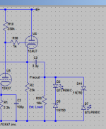
This is discussed in my book. C1 is there to suppress the shot noise of the LED. Without it the SNR can degrade by several dB!Looking at the schematic, what is the reason for C1? So far I have always been happy about getting away without cathode resistor bypass caps when not using a cathode resistor but LEDs...
It has nothing to do with distortion; LED bias does not increase distortion in valve stages. The valves already produce orders of magnitude more distortion by themselves!
Which is great by the way! Highly recommended to everyone and it's beginners friendly.This is discussed in my book.
There is still a "thump" when turning off. So yes.Are output clamping diodes still advisable if a tube rectifier is used for the B+ supply?
They're advisable for any tube circuit. But if you want to avoid them use a neon lamp instead. That will at least limit the output to 90V peak. Also use low-capacitance output caps, like 1uF if you can get away with it, so they charge quickly.Are output clamping diodes still advisable if a tube rectifier is used for the B+ supply?
...use a neon lamp instead.
I can't believe its taken me this long to come across these little miracles. I found this: The Many Uses of the Neon Lamp | Hackaday You can even use them for memory. Slowing 209.59.178.49&c=1&t=43567.24478125
Tubes are in the Earth a century ago than SS, I cant understand how did they was working all that time without SS help.
I'm assuming that's sarcasm. You should chill out and treat this place like a big tent where both the tube purists and SS non haters can get along.
Call it as you want, but from simple regens to entire radar systems were working pretty fine without any kind of semiconductor, so why not a simple audio amplifier can't?
Why should your view, opinions, bias, etc. force others to do things in a way they don't want to? Why are you so dug down that you can't enjoy what you see in common because what you see differently drives you crazy? It's just a hobby.
Last edited:
I like the idea of using diodes. If I understand them correctly they should not produce any noise or distortion when not conducting so that the are inert in normal operation.
It might be fun to use strings of LEDs (protected by Si diode against reverse bias) for a visual indicator of being activated.
It might be fun to use strings of LEDs (protected by Si diode against reverse bias) for a visual indicator of being activated.
Because they did not plug those tube regens into low-voltage components like opamps. The diodes are to protect modern low-voltage components.Tubes are in the Earth a century ago than SS, I cant understand how did they was working all that time without SS help.
We're asking a lot from those LEDs in series with reversed Zeners.
Just saying,
GoatGuy ✓
Probably not worth it just for the bling.
")
Why should your view, opinions, bias, etc. force others to do things in a way they don't want to?
Where and when I wrote that he must do what I said?
Call for medical aid, please. You are ill.
Where and when I wrote that he must do what I said?
Call for medical aid, please. You are ill.
So, you only offer non-binding criticism of SS used in tube circuits? Why say anything then? I am not trying to attack you, in fact, that would be the opposite of my point
- Status
- This old topic is closed. If you want to reopen this topic, contact a moderator using the "Report Post" button.
- Home
- Amplifiers
- Tubes / Valves
- Valvewizard phono diode function and elimination