Hi folks,
So far, I've been winding output transformers with one secondary tap only.
Recently, I started experimenting winding multitap OPTs, and now, with a Williamson style transformer secondary layer configuration, this is where trouble begins.
In my recent prototype:
The primary has 3650 turns, 20 layers.
Each secondary layer has 38 layers (38*3), trifiliar. There are 5 layers
So, logically, there should be the following impedances possible:
1. All in parallel - 74k / 8R
2. 76 turns - 18.5k / 8R
3. 112 turns / 8.2k / 8R
4. 152 turns / 4.6k / 8R
5. 190 turns / 2.95k / 8R
But..
When a series connection of secondaries is made, no matter the order, the series resonance of the coil drops by the double (from 70 to 35kHz) and I see no reason why it should, as the secondary is already low impedance. For this drop in Fres, there must be 4 times increase of capacitance or Ls. It's puzzling.
The funny thing is, different series connections don't influence the Fres. Even one series connection, for example 1//2//3 - 4//5 screws it all and makes no difference to "all layers" in series. The slightly satisfying news is, this resonance is quite damped, since there's no peaking with the intended source impedance.
Although it's not everything...
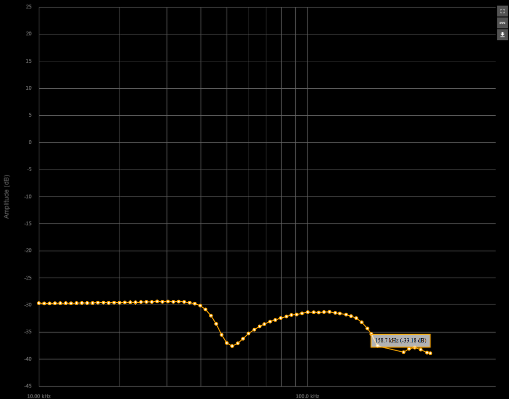
there is a severe dip following at 53kHz, which appears to be a parallel LC resonance, due to the fact the dip increases with source impedance. More unbelievable is the other fact this resonance, if really parallel RLC, is not depending of the main inductance.
Only parallel connection gives the best measurement, with the Fres of 70kHz. It also lacks the severe dip afterwards.
So I'm creating this thread with any hope to discuss this problem with someone who got already familiar with such issues. I see no reason why series connecting secondary layers should bring such a huge, downgrading difference. It would make sense for an interstage transformer, but on an already low Z secondary?
So far, I've been winding output transformers with one secondary tap only.
Recently, I started experimenting winding multitap OPTs, and now, with a Williamson style transformer secondary layer configuration, this is where trouble begins.
In my recent prototype:
The primary has 3650 turns, 20 layers.
Each secondary layer has 38 layers (38*3), trifiliar. There are 5 layers
So, logically, there should be the following impedances possible:
1. All in parallel - 74k / 8R
2. 76 turns - 18.5k / 8R
3. 112 turns / 8.2k / 8R
4. 152 turns / 4.6k / 8R
5. 190 turns / 2.95k / 8R
But..
When a series connection of secondaries is made, no matter the order, the series resonance of the coil drops by the double (from 70 to 35kHz) and I see no reason why it should, as the secondary is already low impedance. For this drop in Fres, there must be 4 times increase of capacitance or Ls. It's puzzling.
The funny thing is, different series connections don't influence the Fres. Even one series connection, for example 1//2//3 - 4//5 screws it all and makes no difference to "all layers" in series. The slightly satisfying news is, this resonance is quite damped, since there's no peaking with the intended source impedance.
Although it's not everything...
there is a severe dip following at 53kHz, which appears to be a parallel LC resonance, due to the fact the dip increases with source impedance. More unbelievable is the other fact this resonance, if really parallel RLC, is not depending of the main inductance.
Only parallel connection gives the best measurement, with the Fres of 70kHz. It also lacks the severe dip afterwards.
So I'm creating this thread with any hope to discuss this problem with someone who got already familiar with such issues. I see no reason why series connecting secondary layers should bring such a huge, downgrading difference. It would make sense for an interstage transformer, but on an already low Z secondary?
So, by connecting the secondaries in series, I'm actually splitting the magnetic fields lines in more "packages", hence the importance of symmetry in interleaving?
I'm starting to suspect the devil hides in the interleaving assymetry which I deliberately made to keep PS interface capacitance low. There is no free lunch in transformer building. The only way that might work, is to have series connections only between the trifiliar wound wires in a layer, but all layers must be kept in parallel, then use the possible connection options, which are 38, 76 and 112.
I'm starting to suspect the devil hides in the interleaving assymetry which I deliberately made to keep PS interface capacitance low. There is no free lunch in transformer building. The only way that might work, is to have series connections only between the trifiliar wound wires in a layer, but all layers must be kept in parallel, then use the possible connection options, which are 38, 76 and 112.
So, by connecting the secondaries in series, I'm actually splitting the magnetic fields lines in more "packages", hence the importance of symmetry in interleaving?
Yup, that's the idea.
I'm starting to suspect the devil hides in the interleaving assymetry which I deliberately made to keep PS interface capacitance low. There is no free lunch in transformer building. The only way that might work, is to have series connections only between the trifiliar wound wires in a layer, but all layers must be kept in parallel, then use the possible connection options, which are 38, 76 and 112.
Capacitance and leakage inductance predictions are quite difficult, standard equations for them sometimes fail with little changes.
Leakage inductance goes as 1/n² being n the number of P-S interfaces, on condition that the first and the last winding is halved, i.e. P/2 or S/2, if not it go higher.
It starts making sense
The assymetric solution I used was a result of my personal attempts of finding a low Ls*Cp winding configuration. This transformer has a P4-S2-P3-S2-P2-S1-P1 setting.
The primary idea of this monstrosity is to keep the outer, highest potential layers far from the secondary, while increasing interleaving with the dropping of P-S potential difference. Hence, if we consider 2 layers of primary per one secondary, the configuration can be divided into the following packages:
P4-S2. It is where the highest Ls is
P3-S2-P1. Lower Ls
P1-S1-P1. Lowest Ls and almost no Cp because the primary layers voltage potentials are close to 0.
But it makes sense trouble might begin when connecting these in series, because of the assymetry of the packages. Especially if a secondary layer has to "steal" from the flux of a neighbor package
A nice, symmetrical solution would be P2-S2-P4-S2-P2,
Last edited:
 Heh... this is familiar and.. to be honest, I stopped doing it, as it is devouring a lot of time. I only calculate the capacitance P/S factor between layers, mostly thanks to the info on Patrick Turner's website. So far, I've predicted the Cp quite accurately, with deviations of 5%. As for Ls, I have a somewhat 30% deviation from my excell spreadsheet simulator. But the error has been quite linear, so instead of fixing it, I just assume some worst additional 30% of leakage.
 How are the measurements taken ???
In circuit sweep frequency response ???
On the bench measurements ??
Differential probes or Single Ended probes with ground clips ??
In sweep, single ended with ground clips, varying the generator resistance for different measurements. This one is taken with 1.2k source resistance.
Im impressed! This is beyond the call of duty. Great to see some one DIYing something so complicated and so important to the sound of tube amps. What I call one of the black arts of audio. Looks like your on your way to becoming a Wizard.
Please, do not call it black art or wizard(ness). As far as it goes for electrical parameters of audio transformers, call it a complex array or RLC networks if you wish, but no black art.
The only wizardly stuff which I've stumbled on is the audible difference between different dielectrics. I suspect the main reason for this is the vibration control of the windings inside. Soft dielectrics, such as paper gives the feeling of more dampening, more controlled sound, while harder dielectrics tend to give a punchier, harsher sound. Which is best? That depends of one's personal taste and system. Nevertheless, I strive for the best electric parameters as possible, then vibration control comes next. Of course, in the easiest in the world, so called 1:1 interstage transformer, one is free to use any dielectric or impregnant, as its influence on Cp will be almost unmeasurable.
Last edited:
Agreed that it is pure engineering...
Been designing and winding transformers for a little over 40 years...
One of the main differences between paper impregnated di-electric vs man-made di-electrics is the voltage gradient of the di-electric ....ie the paper-varnish variant has a much steeper gradient over AC voltage... Also there the bias with applied DC voltage that is different..... There is also corona effect with many of the man-made materials..
Having your windings in series or parallel with significantly affect the self winding capacitance...
Diff probes are a must for measuring transformer sweeps...since with Single ended probes are ground referenced and create a common ground loop between the PRIMARY, SECONDARY, SIG GENERATOR and Network analyzer, thus can mess with the inter-winding capacitance of the OT....
The VPI process is probably the biggest issues...since it can push apart the winding during pressure and not return properly positioned during the vacuum stage..
Last edited:
In sweep, single ended with ground clips, varying the generator resistance for different measurements. This one is taken with 1.2k source resistance.
What is the source ????
What voltage level is applied ???
Thanks for joining in the discussion so thoroughly!
I'm really interested in corona effect in transformers, but not not able to find literature where the phenomena is deeply discussed. Bud Purvine has a lot of posts discussing the corona effect in this forum. Because of my commercial attempt of transformer manufacture in the near future, I want to guarantee maximum safety in these devices.
So far, I'm designing the windings in such ways, to keep high potential layers from low ones as far as possible. The benefit of vacuum impregnation is of course the removal of residual air, due to which corona will exist.
Well, the signal generator and network analyzer are on a same board, they are not separate devices, so I guess no severe ground loops are formed, the length of the probes being the largest factor.
The source impedans in this case is 1.2k, and the applied voltage 1V p-p.
The Williamson scheme for using all turns for both 8R and (nominal) 4R works. But as you have seen you can't do series-parallel connections in any combination you like. Have a look at Lundahl OT's. Your findings explain why they do "apparently odd" and precise series-parallel connections among the various windings.
I remember doing Williamson OT's back as a teenager..... The most interesting Williamson OT from the UK was made by Savage Transformer company back in the 50's... They put V-wedges in the center of the core to bend the lamination plates to help direct the Flux Lines... I think Acrosound had a good Williamson OT and a Ultra-Linear version as well...
Thanks for joining in the discussion so thoroughly!
I'm really interested in corona effect in transformers, but not not able to find literature where the phenomena is deeply discussed. Bud Purvine has a lot of posts discussing the corona effect in this forum. Because of my commercial attempt of transformer manufacture in the near future, I want to guarantee maximum safety in these devices.
So far, I'm designing the windings in such ways, to keep high potential layers from low ones as far as possible. The benefit of vacuum impregnation is of course the removal of residual air, due to which corona will exist.
Well, the signal generator and network analyzer are on a same board, they are not separate devices, so I guess no severe ground loops are formed, the length of the probes being the largest factor.
The source impedans in this case is 1.2k, and the applied voltage 1V p-p.
I don't think 1V Pk-Pk will do the trick.. Definitely not for the low frequency response.... But the high frequency response will need to put some realistic voltage there to get the di-electric to respond properly for capacitance ... Sometimes in-circuit response is best test fixure, since the source impedance is proper as well as the drive voltages...
I see you have 1.2K Ohms as your source impedance....
Keep in mind that this is CLASS-A TRIODE operation, so each valve is about 1.25k average Plate Resistance at the operating point... So the source impedance becomes the two Push-Pull valves in series... since ideally no current flows through the Center-Tap for Class A Push-Pull... So the source impedance becomes 2.5K Ohms... Class-B it would be 1.25k Ohms.... Class AB becomes an interesting mess and average over cycle...
Please, do not call it black art or wizard(ness). As far as it goes for electrical parameters of audio transformers, call it a complex array or RLC networks if you wish, but no black art.
The only wizardly stuff which I've stumbled on is the audible difference between different dielectrics. I suspect the main reason for this is the vibration control of the windings inside. Soft dielectrics, such as paper gives the feeling of more dampening, more controlled sound, while harder dielectrics tend to give a punchier, harsher sound. Which is best? That depends of one's personal taste and system. Nevertheless, I strive for the best electric parameters as possible, then vibration control comes next. Of course, in the easiest in the world, so called 1:1 interstage transformer, one is free to use any dielectric or impregnant, as its influence on Cp will be almost unmeasurable.
Dont get me wrong, I dont mean magic, I mean wisdom, the kind you get from experiance. Because theres so many variables The math and EE only get you so far. I had a EE prof say that designing some antenaes was black art, thats what I meant.
- Status
- This old topic is closed. If you want to reopen this topic, contact a moderator using the "Report Post" button.
- Home
- Amplifiers
- Tubes / Valves
- Advanced issues in audio transformers.