Fisher | Audio Manuals Page 3
in a first, if it is to bring him back to life, buy basic ecc83 (I like JJ), same for 7591, I tried both (EH and JJ) and I prefer them NOT A WORD .
then you have to check the supply capacitors and the signal and decoupling capacitors.
then, once it will work well and you have controlled the values using the diagram above, you can have fun rolling tubes.
be careful with these old devices, their primary power supply is often based on 110 or 220v, while today is often 230 or 240v which does not really pose a problem for the HT, for cons for heating lamps, you often find yourself at 7v or 7.5v instead of the original 6.3v and there is a problem (especially with the lamps jj)
In many models, Fisher took liberties with the 7591's grid to ground resistance limit. The X101D is 1 of those models. Many current production 7591 specimens are intolerant of those liberties and run away.
In the early X100 Fisher used the 7247/12DW7 (1/2 'X7 & 1/2 'U7), instead of the 12AX7 (which is a wimp). "Borrow" from the X100 and rest easy. While I'm among the 1st to castigate JJ about Octal production quality, credit where credit is due. JJ's 12DW7 has proven to be satisfactory.
In the early X100 Fisher used the 7247/12DW7 (1/2 'X7 & 1/2 'U7), instead of the 12AX7 (which is a wimp). "Borrow" from the X100 and rest easy. While I'm among the 1st to castigate JJ about Octal production quality, credit where credit is due. JJ's 12DW7 has proven to be satisfactory.
Attachments
In many models, Fisher took liberties with the 7591's grid to ground resistance limit. The X101D is 1 of those models. Many current production 7591 specimens are intolerant of those liberties and run away.
In the early X100 Fisher used the 7247/12DW7 (1/2 'X7 & 1/2 'U7), instead of the 12AX7 (which is a wimp). "Borrow" from the X100 and rest easy. While I'm among the 1st to castigate JJ about Octal production quality, credit where credit is due. JJ's 12DW7 has proven to be satisfactory.
Eli, I tell you that I am new in the tube, despite my familiarity with the transistor electronics with the tubes I'm bad ... I did not understand anything that you told me before and with the Google translation that does not help things. You tell me that the 7591 do not hold with ecc83? I do not see at all change the schemas because as I tell you with the tubes I am null
Quick Notes:
V1 12AX7/ECC83 is Phono/Tape Preamp Left Channel
V2 12AX7/ECC83 is Phono/Tape Preamp Right Channel
V3 12AX7/ECC83 is Record Output Drive and Tone Control Recovery Right Channel
V4 12AX7/ECC83 is Record Output Drive and Tone Control Recovery Left Channel
V5 12AX7/ECC83 is Power Amplifier Phase Splitter Left Channel
V6 12AX7/ECC83 is Power Amplifier Phase Splitter Right Channel
V7 and V8 are 5791 Output Tubes Left Channel
V9 and V10 are 7591 Output Tubes Right Channel
V1,V2, V3, V4 MUST be in to operate the 7591 Output Tubes - their heaters are wired in series and used as the cathode bias resistor for the output tubes.
Hope this helps,
Ian
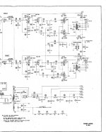
Study the schematic, which can be found here.
Ian is correct. Fisher employed a "Cheap Charlie" technique for preamp tube DC heater power.
 The audio signal modulates the current flowing in those preamp tubes' heaters. YUCK!
IMO, some re-engineering is in order. Construction of a regulated 600 mA./12 VDC heater supply is easy enough. Each channel should have, at a minimum, its own RC network for biasing the O/P tubes. Some members will prefer that each O/P tube have its own dedicated RC network. FWIW, I like a network that's shared by a PP pair, as matching constraints are slightly relaxed. Close transconductance (gm) matching within a PP pair is always necessary. When the RC bias network is shared, minor differences in cathode current will automatically correct. As constructed by Fisher, the amp requires a quartet of O/P tubes that are closely matched in both gm and cathode current, which adds to ownership costs.
Ian is correct. Fisher employed a "Cheap Charlie" technique for preamp tube DC heater power.
The audio signal modulates the current flowing in those preamp tubes' heaters. YUCK!IMO, some re-engineering is in order. Construction of a regulated 600 mA./12 VDC heater supply is easy enough. Each channel should have, at a minimum, its own RC network for biasing the O/P tubes. Some members will prefer that each O/P tube have its own dedicated RC network. FWIW, I like a network that's shared by a PP pair, as matching constraints are slightly relaxed. Close transconductance (gm) matching within a PP pair is always necessary. When the RC bias network is shared, minor differences in cathode current will automatically correct. As constructed by Fisher, the amp requires a quartet of O/P tubes that are closely matched in both gm and cathode current, which adds to ownership costs.
I'll disagree with Eli's first point - there is no audio in the preamp tube heaters as the cathode current of a class A push-pull amplifier is near constant DC - and it's bypassed for AC as well.
Best reports on modern 7591s have been on Tung-Sol brand, which are the original size - JJ are larger, EH are larger yet. If your amp has a cover, it matters. Matched set is necessary. R55-58 should be changed to 180K, C21-24 should be changed to .1 uF - this to allow for likely greater grid leakage in modern 7591 tubes.
ECC83s don't need matching - four of the six are inside feedback loops that control gain. The phase inverter stage voltages should be checked - a direct-coupled pair of stages can be touchy. Some have had problems with European or Russian tubes here, American brands seem a better match for this circuit (anything will work if you're willing to change resistor values...).
I'll disagree with Eli's first point - there is no audio in the preamp tube heaters as the cathode current of a class A push-pull amplifier is near constant DC - and it's bypassed for AC as well.
Best reports on modern 7591s have been on Tung-Sol brand, which are the original size - JJ are larger, EH are larger yet. If your amp has a cover, it matters. Matched set is necessary. R55-58 should be changed to 180K, C21-24 should be changed to .1 uF - this to allow for likely greater grid leakage in modern 7591 tubes.
ECC83s don't need matching - four of the six are inside feedback loops that control gain. The phase inverter stage voltages should be checked - a direct-coupled pair of stages can be touchy. Some have had problems with European or Russian tubes here, American brands seem a better match for this circuit (anything will work if you're willing to change resistor values...).
Thank you all Tom I understand better what you say I'm good in electronics but not on the tubes, according to you the only change that would be to replace the 4 resistors 330k R55 ,R56,R57 and R58 by a 180k and 4 capacitors 0,047µf C21 ,C22,C23, C24 by 1µf polypropylène? This will allow to adapt the new tube manufacture to the amp
Last edited:
My bone of contention with simply lowering the 7591 grid to ground resistance value is the wimpy (HIGH RP/LOW gm) nature of the 'X7 triode. While I lack rigorous proof, it seems pretty obvious that switching from the 7247/12DW7 was done as a cost cutting inventory control measure. Avery Fisher did not become extremely wealthy by accident.
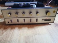
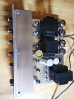
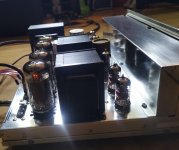
Hello, this is finally the Fisher works !!!! The resistances and capacitors replaced and now he sings without problem ... Fortunately the original transformer and well in 240v (2x120v) and not in 220v the filaments are well fed in 6.3v and all voltage ht are exactly as in the manual. I thank you for the advice, here are some photos for fun
Attachments
- Status
- This old topic is closed. If you want to reopen this topic, contact a moderator using the "Report Post" button.
- Home
- Amplifiers
- Tubes / Valves
- Fisher x-101d