Hell everybody, finally had some time of my own to work on the amp. I need an advice about derating a damper diode, 6CD3 (1.5A steady peak current, 350ma dc output current).
My case, the amp will draw ~220ma for 4xkt88, and about ~20ma for 3x12au7 tubes.
The psu will be, PT 400-0-400v at 500ma, primary 3ohm, secondary 25ohm > 2xUF5408 in series > 6CD3 diode > first cap 40uf > choke 2H 18ohm 400ma > second cap 270uf.
Plotted the data into psud, and if i use 6CD3 as rectifier, steady peak current is about 1.25A which is within the datasheet peak current value.
Will the diode survive? I don't know how much should i derate the value. The diode won't pull rectifier duty, this part is taken care of by UF5408.
Should i add resistor between damper and first cap? Would this have a negative impact on the sound, dynamics ?
Thanks
My case, the amp will draw ~220ma for 4xkt88, and about ~20ma for 3x12au7 tubes.
The psu will be, PT 400-0-400v at 500ma, primary 3ohm, secondary 25ohm > 2xUF5408 in series > 6CD3 diode > first cap 40uf > choke 2H 18ohm 400ma > second cap 270uf.
Plotted the data into psud, and if i use 6CD3 as rectifier, steady peak current is about 1.25A which is within the datasheet peak current value.
An externally hosted image should be here but it was not working when we last tested it.
Will the diode survive? I don't know how much should i derate the value. The diode won't pull rectifier duty, this part is taken care of by UF5408.
Should i add resistor between damper and first cap? Would this have a negative impact on the sound, dynamics ?
Thanks
A couple thing to keep in mind when designing power supplies for tube amplifiers... It is typical to know know full power numbers as well as idle numbers.... The power amplifier analysis should be done at full power output...So you current draw is the averaged current over cycle... This should include the screen currents which will be over 30mA for each KT88 when at full power clean... As you increase filter cap size, the conduction angle decreases, thus higher PEAK current which is what you need to limit to keep the rectifier tube from damage... So the Data sheet indicates 1.5A PEAK and also 12W plate dissipation... De-rating guidelines depend on the application...Most Military de-ratting for diodes is 50% to 80%..... It all depends on longevity.... Check your plate dissipation doesn't exceed... Either add a resistor to current limit or reduce the value of the first filter cap to increase the conduction angle, thus reducing PEAK current.. I think 1.2 is 80% of MAX PEAK ....You should be OK...I think you would conduct your own MTBF experiment...
Last edited:
I've not used this one but have found damper diodes to seriously robust.
There are those who mention the specification note that they are unsuitable as general purpose rectifiers. I think that is mainly due to the long warmup time.
What is the purpose of the UF5408s?
I'm using UF5408 for rectification. One 6CD3 as slow start, and to eliminate a part of the silicon diodes hash. And has much lower voltage drop than a classic tube rectifier. I'm thinking is a nice feature to have, as long as i figure out if i'm safe
") .
.You should be good as is with the 6CD3. If you're worried, use 100R in series with each plate. I use 6D22S for a similar amp...
I wonder if you used the resistors for 6D22S ? And if you remember, what was your transformer impedance?
A couple thing to keep in mind when designing power supplies for tube amplifiers... It is typical to know know full power numbers as well as idle numbers.... The power amplifier analysis should be done at full power output...So you current draw is the averaged current over cycle... This should include the screen currents which will be over 30mA for each KT88 when at full power clean... The rectifier tubes will only see PEAK current not average current... As you increase filter cap size, the conduction angle decreases, thus higher PEAK current which is what you need to limit to keep the rectifier tube from damage...
I'm going plot the numbers again in psud, with full power. The damper will be use only as delay and to isolate silicon diodes hash.
But i don't know how much to derate the damper diode steady peak current, so i know i'm in a safe zone.
I think that is mainly due to the long warmup time.
Compactron tubes in the great majority are ready after 11seconds to start conducting.
Attachments
Yes. Damper diodes in their circuit have high voltage pulses at their cathode, and lower (+B) DC at their anodes, so they need high insulation cathode/heater, and the anode needs normal insulation. This is why some of them has the cathode at the top cap, mainly 9 pin miniature tubes."Compactron tubes in the great majority are ready after 11seconds to start conducting."
What makes these different to all the other damper diodes I've encountered that have massive insulation between the heater and cathode, and take an age?
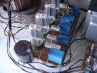
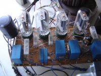
In my project I'm using a bridge (pics below) running choke input filter to give ±275V from a home made toroidal transformer. They are 6AX3 or 6BE3 tubes (same heater rating) but the former have higher anode dissipation, copper made. The former are clear silver-like metal.
Osvaldo, the two tubes you mention are designated as rectifiers, not as damper diodes, so I'd expect their warm-up time to be faster as they don't have special cathode insulation.
My argument remains, that damper diodes are not recommended as rectifiers because of warm-up time rather than any other limiting factor.
My argument remains, that damper diodes are not recommended as rectifiers because of warm-up time rather than any other limiting factor.
"I'm using UF5408 for rectification" Maybe I'm missing something but that's what the 6CD3s will do. So I still don't see the need for the silicon rectifiers… Please put me out of my misery
LOL.
I would imagine "belt and suspenders" idea, …
since there's no evidence for the UF's in any of the diagrams.
Just saying,
GoatGuy ✓
Osvaldo, the two tubes you mention are designated as rectifiers, not as damper diodes
Are you sure?
Attachments
mea culpa
Osvaldo,
I was too quick in my glance at the data sheets. Even though the sheets I read said "half wave rectifier" you are quite right that they are designated as damper diodes.
So the next questions is: Why do these types warm-up faster than others?
And the next question: Where can I buy some?
Osvaldo,
I was too quick in my glance at the data sheets. Even though the sheets I read said "half wave rectifier" you are quite right that they are designated as damper diodes.
So the next questions is: Why do these types warm-up faster than others?
And the next question: Where can I buy some?
I believe that they had been working in better metals/alloys. And perhaps the need for competition with transistors. I knew about tube TV that never turned off heaters completely to accelerate start up, say, have pic in the CRT.
I have some guys there in USA who have them. This is one of them:
Jim Cross <jim@vacuumtubesinc.com>
I have some guys there in USA who have them. This is one of them:
Jim Cross <jim@vacuumtubesinc.com>
I think the sleeve between the heater and cathode is ceramic in the European damper diodes. No idea about the compactrons.
I worked for a TV manufacturer. We had a range of solid-state TVs that gave an instant picture. The CRT heaters were fed 3V in standby. The CRT had special cathode material to support this. The CRTs lasted longer than many "regular" CRTs.
I worked for a TV manufacturer. We had a range of solid-state TVs that gave an instant picture. The CRT heaters were fed 3V in standby. The CRT had special cathode material to support this. The CRTs lasted longer than many "regular" CRTs.
"I'm using UF5408 for rectification"
Maybe I'm missing something but that's what the 6CD3s will do. So I still don't see the need for the silicon rectifiers...
Please put me out of my misery
This is what i'm doing. I need two 6cd3 for rectification, and i'm using only one.
An externally hosted image should be here but it was not working when we last tested it.
- Status
- This old topic is closed. If you want to reopen this topic, contact a moderator using the "Report Post" button.
- Home
- Amplifiers
- Tubes / Valves
- How much should i derate a damper diode ?