I am having trouble understanding how fixed bias provides higher maximum power over a cathode biased output stage with a bypass cap on the bias resistor. If you design your power supply to provide the desired Vp-k and Rk is bypassed so that there is no degeneration how does the self biased stage lose any potential output power?
Yes. Using CCS bias is even worse. A partial solution is to bias the valve 'hot' for small signals so that when 2nd-order distortion makes it 'colder' it is still at a reasonable bias point. Valve dissipation limits may constrain this, though.
In addition, it is likely that the cathode resistor voltage drop will use up 5-10% of the supply rail voltage.
In addition, it is likely that the cathode resistor voltage drop will use up 5-10% of the supply rail voltage.
two separate cathode resistors
Follow up question: why does MO Valve assert "it is essential to use two separate cathode resistors" for each of the self biased push pull output stages. I have followed their advise in my builds, but shared cathode resistors are very common in many commercial amplifiers.
Follow up question: why does MO Valve assert "it is essential to use two separate cathode resistors" for each of the self biased push pull output stages. I have followed their advise in my builds, but shared cathode resistors are very common in many commercial amplifiers.
Attachments
but shared cathode resistors are very common in many commercial amplifiers.
It saved the cost and labor of one resistor. Most of all, it mandate the buying of matched pair tubes down the line. But times are different now.
Cathode bias will place the cathode on 30-50V, this reduces theI am having trouble understanding how fixed bias provides higher maximum power over a cathode biased output stage with a bypass cap on the bias resistor. If you design your power supply to provide the desired Vp-k and Rk is bypassed so that there is no degeneration how does the self biased stage lose any potential output power?
plate <> cathode voltage the same amount. There is your power loss !
I believe what he's saying is why can't the amp be supplied with enough voltage to give max power output for the tube even with a cathode biasing. It's obvious that if you take a fixed bias circuit producing max power and swap in a cathode resistor for biasing you'll lose some available power.
Fixed bias gives more power for any given cathode to anode voltage. So considering the loss of voltage because of the cathode resistor is not relevant to the argument.
The reason is what I eluded to in post 2 and can be explained by running this test:
In a cathode biased output valve, measure the cathode voltage at zero signal.
Now increase the signal to the point of clipping or a rapid increase of distortion and measure the voltage again.
It will be higher.
Two things are happening here.
1. The A-K voltage is diminished slightly - this is not a big deal.
2. The G-K voltage is increased - this is what limits the power.
Why is this happening?
To elaborate on post 2, the waveform at the anode is becoming asymmetrical, leading to the average current through the valve to increase thus raising the cathode voltage.
Follow up question: why does MO Valve assert "it is essential to use two separate cathode resistors" for each of the self biased push pull output stages. I have followed their advise in my builds, but shared cathode resistors are very common in many commercial amplifiers.
For lower distortion Class AB is better with separate resistors and class A with common resistor.
Reduction of plate voltage is one reason. But the big one is that class AB operation becomes possible with fixed bias. In class A, peak cathode current is twice idle current, no more. In AB, peak current can be higher, while opposite tube is cut off. Average current increases, which would increase bias voltage if cathode bias were used, causing crossover distortion. So cathode bias is limited to class A operation (except for brief peaks). For the same reason, idle current can be reduced - peak current is limited by the tube, not twice idle current.
It saved the cost and labor of one resistor. Most of all, it mandate the buying of matched pair tubes down the line. But times are different now.
...plus one electrolytic, not to forget. Yes, parts costs were relatively high in the heydays of tube technology, when most of our well known designs originated.
Best regards!
...understanding how fixed bias provides higher maximum power over a cathode biased output stage...
....this test: In a cathode biased output valve, measure the cathode voltage at zero signal. Now increase the signal to the point of clipping or a rapid increase of distortion and measure the voltage again. It will be higher.....
A correctly-loaded self-biased high-fidelity audio amplifier should have "constant" current and cathode voltage at any signal level. If the bias varies more than a little, gain varies, which is anti-Fidelity.
Yes, we normally observe "some" bias rise, due partly to the natural curvature of tubes, and also the desire of designers/marketers to push the limits and get bigger power numbers for the price. And since Hi-Fi amps are rarely clipped hard, a fat cathode cap forestalls bias-shift until the music sounds like crap.
So a properly loaded self-bias amplifier must approach a classic Class A condition. The idle power is ALL the power that the amplifier has to work with. It can waste it as heat, or divert it to the load (output), but can't suck more power from the supply (or it gets out of Hi-Fidelity). Maximum Sine output is <half the total dissipation (usually 40% for pentodes).
This dependence on dissipation at idle limits the power two bottles can deliver.
A fix-bias amplifier can, in principle, be idled stone-cold, no idle current; because with signal it will increase its power demand to feed the load. While idle dissipation can't really be zero, it can be no-problem. Dissipation is higher at half and full power, but still less than the Class A case.
Say you want to wash your dog with a fire-hose. In Class A you leave the hose flowing wide-open, deflect a little water onto your dog, let the rest go to waste. In Class B you have a valve and only pass the amount of water your dog needs.
Reduction of plate voltage is one reason. But the big one is that class AB operation becomes possible with fixed bias. In class A, peak cathode current is twice idle current, no more. In AB, peak current can be higher, while opposite tube is cut off. Average current increases, which would increase bias voltage if cathode bias were used, causing crossover distortion. So cathode bias is limited to class A operation (except for brief peaks). For the same reason, idle current can be reduced - peak current is limited by the tube, not twice idle current.
Absolutely right. Fixed bias allows running push-pull amps in class AB mode, with higher anode voltage, to get more power.
This is why I follow PRR's postsSay you want to wash your dog with a fire-hose...

Say you want to wash your dog with a fire-hose. In Class A you leave the hose flowing wide-open, deflect a little water onto your dog, let the rest go to waste. In Class B you have a valve and only pass the amount of water your dog needs.
But it's not all roses and flowers. Even in cases where the devices are very linear by default there are trade-offs. I have done a lot of experiments with the 45 in PP. The class A amplifier is less efficient however at lower and medium level has significantly less distortion despite the lower output power.
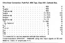
If you compare the class AB1 amplifier working at 300V/32-33 mA per tube with self bias into 5K plate-to-plate (common cathode resistor of 1K) and the class AB1 amp fixed biased at 275V/20mA into 4K plate-to-plate they both deliver about 7.5W with 1% THD but there are differences that one cannot see in the data-sheet. Important differences for me. For someone else probably not. It depends on the way it's used, if some feedback is used etc.....
They seem to be equivalent but in terms of distortion vs power they aren't. The self biased amp has up to 3-4 times less distortion up to 2-3W output. The self biased amp reaches then the 1% a bit quicker towards the max output (but still a soft clipping amp) also because there is some bias shift that allows to swing 70V peak with about 63V quiescent bias. Fact is that at 1W output the self biased amp can have as low as 0.1-0.2% THD while the fixed bias is no less than 0.4 %. Ot at least I haven't been able to do better..... One might see this also drawing the composite tube curves where it will be clear that biasing at low current results in a bit worse linearity. This gets significantly worse for less linear tubes.
The class AB1 amp with self bias can be used in way which is not straightforward for the fixed bias. If I double the plate load the distortion figures vs output power of the self biased amp do not change significantly into the variable load. That's not the case for the fixed bias amp. So if a use a 10K transformer I will get some 5W in class A and the amp will be able to drive 8R speakers with 4R minimum impedance without any trouble.
I have made the 45 example also for another reason. The separate self-bias resistors are almost redundant in this case. Distortion figures are basically the same. For class A, AB1 and even AB2 with self bias only common cathode resistor is recommended. As always, there are exceptions.
")
Last edited:
- Status
- This old topic is closed. If you want to reopen this topic, contact a moderator using the "Report Post" button.
- Home
- Amplifiers
- Tubes / Valves
- how does fixed bias increase max power?