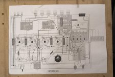
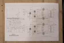
I bought a Raphaelite DPK34 tube amp kit few years ago. I got most of the way through assembly but hit a road block and then didn't have the time to finish. So it has been in a box in my basement for the last 2 years. I just pulled it out again after getting some help on another forum, and I don't feel comfortable finishing it - I don't know how to read the schematic, and the wiring diagram is unclear.
Is there any chance someone in the Chicago area would be willing to finish this project? I have cash and am not in a hurry. I know it's a long shot but I figured I'd reach out before listing it for sale. (If soliciting help is against the rules I apologize - didn't see anything about it on the rules page).
Is there any chance someone in the Chicago area would be willing to finish this project? I have cash and am not in a hurry. I know it's a long shot but I figured I'd reach out before listing it for sale. (If soliciting help is against the rules I apologize - didn't see anything about it on the rules page).
Attachments
Linked this to an old friend in Chicago - no idea if he'll "bite".
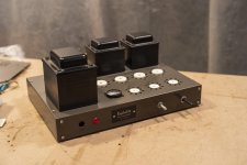
But really the project shouldn't be too daunting. It looks as if you've practically completed it, and as long as you check it for mistakes, and follow the setup procedure, you'll have a working amp.
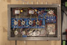
In fact with the detailed photo you provided, sharp eyed members can probably check much of what you've done visually.
But really the project shouldn't be too daunting. It looks as if you've practically completed it, and as long as you check it for mistakes, and follow the setup procedure, you'll have a working amp.
In fact with the detailed photo you provided, sharp eyed members can probably check much of what you've done visually.
Linked this to an old friend in Chicago - no idea if he'll "bite".
Thank you!
I know it's close. There's a good chunk of wiring left for the tube sockets, as well as RCA connections, input switcher, power input and switch, and a few miscellaneous things. The RCA connections I'm fine with, and the power/switch connection I could figure out with a little help. I'm an idiot about the rest, and don't know how well I would be able to check my own work. I have no idea how the amp works. Considering the potential harm these things can do I'd rather leave it to someone more experienced. My local electronics repair guy was too busy for it unfortunately.

some of the wires of the same color are twisted and I can't trace which wire is which.
If the twisted wires are for the filaments, the two wires would be interchangeable, so it wouldn't matter which is which.
That helps, thanks.
I think you can do it, just get some beer and a quiet place.
That's a very good wiring layout, japanese style.
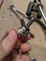
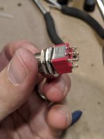
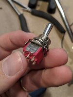
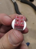
So knowing it doesn't matter which wire is which for the tube sockets really helps. Another thing I couldn't figure out is which tabs to use on the switch. There are 6 tabs (2 rows of 3) but only two wires, and I couldn't find a diagram of the switch online. It says T-80T Salecom on the side.
Also, if I do actually get all of the wiring done, what steps do I need to take to double check that everything is good? If I turn it on and it doesn't work, I do not want to go back in there with the charged caps and all.
Also, if I do actually get all of the wiring done, what steps do I need to take to double check that everything is good? If I turn it on and it doesn't work, I do not want to go back in there with the charged caps and all.
power on switch or source selector ?
for the rest, the start-up / verification procedure is just logic.
already, a last visual inspection of the wiring.
no tubes in place.
power on
control of the heating circuit
control of the supply voltage ht on each tube
control of power on the output transformers
control of the negative voltage of the bias circuit +
pre-setting according to B + and the type of power tubes used.
and finally, connection of a power resistance of 8ohm 10w on each output opt, short circuit of the input rca and put under
tension with the small tubes to see if everything is ok (always keep your finger on the switch in case ...) then finally test with the power tubes (I start one side after another),
control of bias power tubes on a resistance of ten ohm per lamp to see if the tube delivers current, and finally control of the output voltage hp and if all goes well, we connect a source and speakers "suicide" and, let the music !! or not ...
I must have forgotten but people more qualified than me will correct my mistakes / omissions
For the look of your soldering work, I also think you should have no problem finishing it. Just make sure you have a good Digital Volt Meter at hand. The tricky part is the source selector switch. Ohm it out before and after connecting. Also ohm out the power path for shorts before you turn it on. Do this in multiple steps. Take pictures and ask questions before the next step. I think there are a lot of folks here will help you.
power on switch or source selector ?
Power on switch, for now.
I haven't looked too close at the source selector yet and will post another reply for help with that most likely.
can you take a pics of a rear and front of power switch please
Here is the power switch.
Attachments
- Status
- This old topic is closed. If you want to reopen this topic, contact a moderator using the "Report Post" button.
- Home
- Amplifiers
- Tubes / Valves
- Raphaelite DPK34 kit assembly help