I am planning to build a 45 se amp .
As I would like to avoid to use Elco's my intention is to use negative bias to avoid the use of a bypass elco as is used with fixed bias at the cathode .
So far so good .
But I allso would like to use ac heating and there I seem to get stuck .
I can't find any suitable diagrams on how to do this .
So It makes me wander if this set-up is possible at all ?
Last edited:
I was working on a 45-SE a while ago (but the project got stuck due to lack of time). I got the bug from this thread. My last design version is in post 116. The driver is direct coupled to the 45 grid, and there is no electrolytic cap anywhere in the signal. The circuit could be done with film caps everywhere. Maybe this thread + design is useful for you.
Sorry people,
I was making a thinking error on how to ever measure the current over a humpot ....
I just have to put a 1 ohm resistor in series to ground")
Btw, I don't mind using caps in the signalpath, in fact I was planning to use a coupling cap between the driver (C3M) and the 45
I was making a thinking error on how to ever measure the current over a humpot ....
I just have to put a 1 ohm resistor in series to ground
Btw, I don't mind using caps in the signalpath, in fact I was planning to use a coupling cap between the driver (C3M) and the 45
Look at Thomas Mayers 46 amp. AC heating and no elcos
VinylSavor: Single Ended Amplifier Concept, Part 7
VinylSavor: Single Ended Amplifier Concept, Part 7
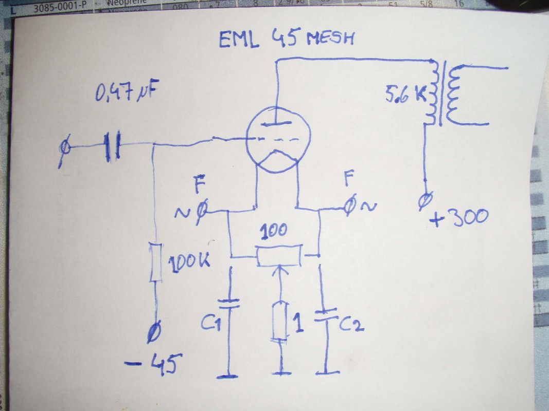
C1 & C2 are just an idea, good idea or not ?
What bias current are you aiming at? You might have to adjust the values in the cathode resistor network.
Yes thank you Nightpuma, I've came across that one.
It definitely looks promising only it has cathode bias.
VinylSavor: Single Ended Amplifier Concept, Part 7
And the placement of those 4 30uF's is a new concept to me.
I just wish my power transformer arrives soon so I can start building
I'm going to apply negative bias voltage
It definitely looks promising only it has cathode bias.
VinylSavor: Single Ended Amplifier Concept, Part 7
And the placement of those 4 30uF's is a new concept to me.
I just wish my power transformer arrives soon so I can start building
According to the data-sheet 39mA @ 300VWhat bias current are you aiming at? You might have to adjust the values in the cathode resistor network.
I'm going to apply negative bias voltage
 Copyrighted image removed from the post above.
According to the data-sheet 39mA @ 300V
I'm going to apply negative bias voltage
The voltage drop across your cathode resistor network would be 0.039 A x 26 Ω = 1 V. With your -45 V grid voltage, you end up at a grid-cathode bias of -44 V. According to the EML curves, this would give a bias current of about 70 mA at 300 V. You need to fix the cathode resistor values or the grid bias voltage.
As I am a self building music lover, my intention is to build the amp as straight forward as possible .
From experience I found that the less is more approach suits my needs the best ,
Oh, and I do like chokes in the power supply, they give dynamics.
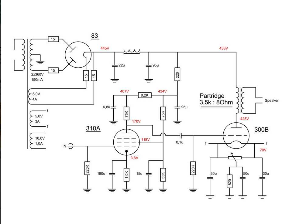
This is the diagram of a 300b that I ran into that I like :
From experience I found that the less is more approach suits my needs the best ,
Oh, and I do like chokes in the power supply, they give dynamics.
This is the diagram of a 300b that I ran into that I like :
An externally hosted image should be here but it was not working when we last tested it.
Last edited:
From experience I found that the less is more approach suits my needs the best ,
Oh, and I do like chokes in the power supply, they give dynamics.
I can relate with this very much. In my recent KT66 project I used chokes as loads for the driver tubes and as filters in the B+ power supply. It turned out that I went a bit too far with the choke loads for the driver tubes. A solid-state constant-current source (CCS) measured more linear and with less noise pickup. The CCS was much cheaper, much smaller, and sounded better. That's why my 45-SE design has a CCS load.
There is also the good old parafeed 45SE design by John Tucker. The article about it is a good read. It used to be on the Positive Feedback website, but I can't find it there anymore. I attached a PDF of it.
Attachments
And it's in working state :

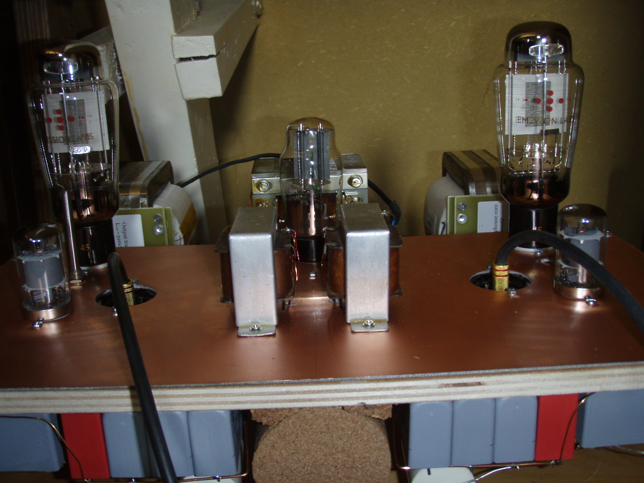
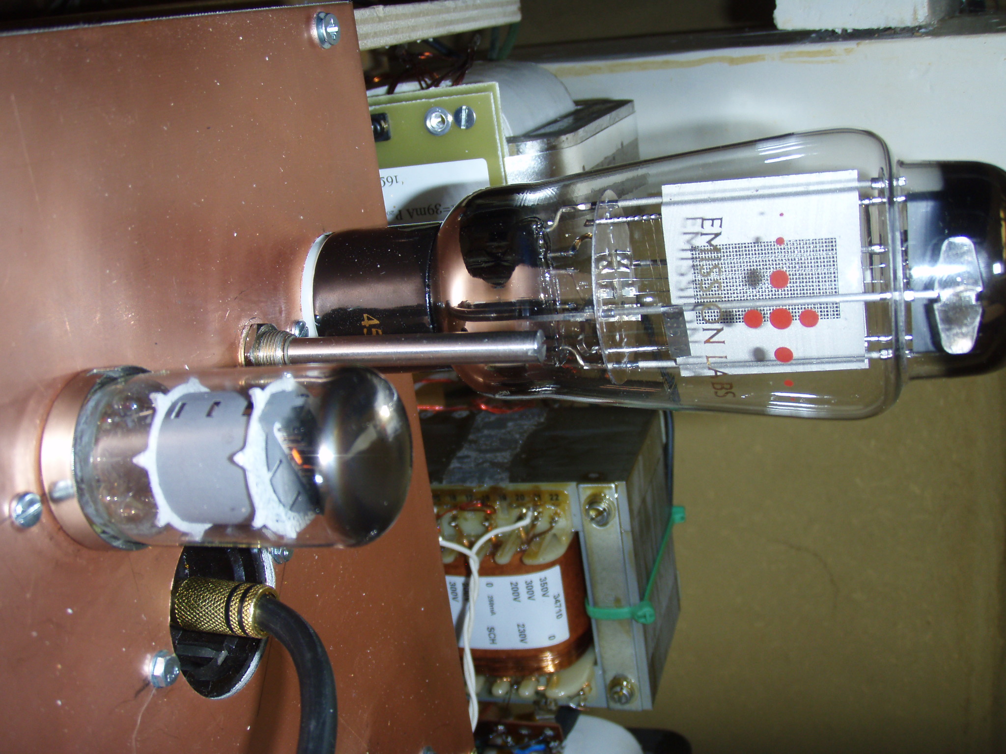
The Telefunken C3M and EML 45 mesh
I am happy with this build, it gives a enormous deep rich and detailed sound-stage with lot's of dynamics .
The depth however can be made undone by adding elco's in the power-supply, I never was a fan of elco's but adding them in this build is disastrous ........
MKP only here
Raaf61,
The 83 is a mercury vapor rectifier, it only has a 15V forward voltage drop, and it may have a pretty glow. That may be the 2 reasons it was included in that circuit.
But mercury vapor rectifiers usually need special treatment. You should warm up the mercury vapor rectifier's filament before you activate the B+ HV secondary. Also, mercury vapor rectifiers can create broadband noise. Some applications recommend shielding the tube (which would prevent you from seeing the blue glow).
Why not just use solid state diode rectifiers? Then increase the resistance of the two 15 Ohm resistors that were between the B+ HV secondary and 83 plates, to get an additional 15V drop when using solid state rectifiers?
Solid state rectifiers do have a quick B+ startup. So . . . A diode from the 300B (or 45) grid (anode end of the diode), to one end of the 300B (or 45) filament (cathode of the diode) will prevent the grid from going more than 0.6V positive when the "quick" B+ comes up.
Just my opinion.
Last edited:

Telefunken data says that C3m, in triode mode, have G2 and G3 connected to anode (via a 75-100 ohm resistor, usually).
And indeed, C3m, C3g, D3a, E180F.... sounds more comfortable when both grids are connected to anode. Try it.
Nice job, BTW
https://frank.pocnet.net/sheets/128/c/C3m.pdf
Please look at this scheme of triode mode D3a-45 SE amp on Ale Moglia's site.
This must sound like charm.
45 SE Amplifier – revisited – Bartola(R) Valves
Raaf61,
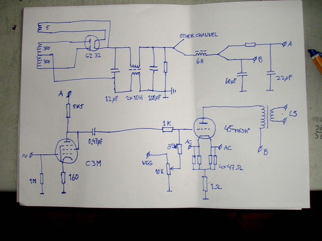
You need to put the 1k Ohm grid stopper on the other side of the 82k Ohm resistor. The 1k Ohm needs to be connected directly to the 45’s socket grid tab. You do not want anything else connected to that grid tab.
I hope you do not have a lot of common mode noise coming from your Power Mains. That is the only reason to use the 2 x 10H common mode choke.
Instead, you could use the 12uF, a single10H choke, 100uF and bleeder resistor. Connect the HV B+ center tap Directly to the bottom (-) of Both the 12uF, and bottom (-) of the 100uF caps. That will create a ’ local loop’ of high current transients that are not “transmitted” out to the rest of the circuit grounds. Then connect that high current ‘local loop’ ground with a separate wire to the (-) of the 60uF caps and the 20uF caps, and then to the rest of the circuitry grounds. You might be able to parallel the 2 x 10H common mode choke and get a good enough 5H choke, but if there is not enough core it will saturate on the 2 X line frequency (100Hz or 120Hz). That is because it is no longer used in common mode (may require more core).
Let the ground of the RCA input connector be insulated from the chassis by using plastic shoulder washers. Connect the RCA input connector ground to the bottom of the 1Meg input resistor, and the bottom of the 160 Ohm cathode resistor. Then connect from there to the chassis ground.
Connect the 60uF, 20uF, 1 Ohm, 10k pot, to the chassis ground.
Be sure to ground one end of the output transformer secondary (safety first, the primary could short to the secondary).
If your power mains has a ground connection, Use an IEC socket, 3 wire power cord, and connect the IEC socket ground to the chassis ground.
I think I covered the connection of all the grounds. The idea is to reduce the ground loops, and to insure safety.
With AC on the 45 filaments, you might expect to get from 1mV to 5mV or more hum at the amp output. It will depend on the 45 tube, versus the match of the 47 Ohm resistors. The tube filament ends may not have the same pseudo center as the 47 Ohm resistors center. A pot may only reduce the hum a little bit (2 each 47 Ohm resistors, and a 100 Ohm Pot). The junction of the two 47 Ohm resistors goes to the pot wiper, and to the 1 Ohm resistor. The ends of the pot goes to the filament ends.
First, try using the AC filaments, you’re already there (need 2 separate 2.5V AC windings). Lowest hum is obtained with DC on the 45 filaments; but that requires two separate 2.5VDC supplies, so you can sense (individual 1 Ohm) and adjust the individual plate currents. DC filaments will also get rid of the intermodulation of 2x line frequency (100Hz or 120Hz) that intermodulates (appears on) each and every of the musical tones that come through the amp. You should get less than 1mV of hum. I keep pushing my amplifiers hum down, and often get 100uV or less hum.
Last edited:
- Status
- This old topic is closed. If you want to reopen this topic, contact a moderator using the "Report Post" button.
- Home
- Amplifiers
- Tubes / Valves
- 45 SE amp