That's how I started but found this connection better sounding . I might reverse it again to double check .And indeed, C3m, C3g, D3a, E180F.... sounds more comfortable when both grids are connected to anode. Try it.
Ale Moglia has a to tech approach for my taste .Please look at this scheme of triode mode D3a-45 SE amp on Ale Moglia's site.
Zeners and ferrite in a Tube amp .......... the horor
 Really if there's one way to kill the soundstage of a amp , use ferrite .
I'll try thatRaaf61,
You need to put the 1k Ohm grid stopper on the other side of the 82k Ohm resistor.
The 1k Ohm needs to be connected directly to the 45’s socket grid tab. You do not want anything else connected to that grid tab.
I have compared a single core 10H and this double core, the double gives more dynamics .I hope you do not have a lot of common mode noise coming from your Power Mains.
That is the only reason to use the 2 x 10H common mode choke.
this is the situationLet the ground of the RCA input connector be insulated from the chassis by using plastic shoulder washers.
Connect the RCA input connector ground to the bottom of the 1Meg input resistor, and the bottom of the 160 Ohm cathode resistor. Then connect from there to the chassis ground.
Might be safer but affects the sound qualityBe sure to ground one end of the output transformer secondary (safety first, the primary could short to the secondary).
If your power mains has a ground connection, Use an IEC socket, 3 wire power cord, and connect the IEC socket ground to the chassis ground.
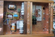
This amp is not finished as it is my first DHT build . If you look at the picture you'll notice a humpot left and the four 47R resistors right . The left is more quite indeed . First I would like to see if I can get this amp quite on AC before considering DC .With AC on the 45 filaments, you might expect to get from 1mV to 5mV or more hum at the amp output. <snip>
Thanks for your input 6A3sUMMER
I got the tubes from Jacmusic. EML also do a 45 with center tap on the Cathode, but not for the mesh My speakers are PHY H21 LB 15 Sag in open baffleWhere did you get your Emission Labs tubes?
Last edited:
ok, so your original post was asking for a suitable design for a 45 amp that uses not electrolytic capacitors... then a few days later you post pictures of the amp you built without electrolytic capacitors...
Ever ask yourself why Electrolytics sound so "bad" in your design? They work perfectly well in many other designs. Food for thought perhaps...
Besides that:
The chokes in your power supply are only there for smoothing. If you change over to a choke input power supply then you will likely experience an epiphany.
I hope your Mesh 45 never runs away. There are some advantages to cathode bias. To each their own, but don't be surprised if it ever happens.
Ferrite beads work well on filaments if needed, but I never needed them on the c3m. Maybe you used them in the wrong places previously.
Also, C3m should really be run in pentode. You are getting very little swing to drive your 45 grids as it is...
Last edited:
Hello
If you change over to a choke input power supply then you will likely experience an epiphany.
Because Raaf61 is from my country i already send him a private message that if he really wants his amplifier to make a big leap he should switch to a choke input. It is not a difficult thing to do . Just take care that you install a bleeder to make it work like a choke input no matter what happens. He already has a 20Henry choke from lundahl which is a good start. He probably will need another transformer because right now he is using 300-0-300 with cap input and the highest tap on his present transformer is 350-0-350. Should be higher depending on the current being drawn. Greetings, Eduard
Ps in the attachment you can see my choke input line pre amplifier where a shunt regulator with tubes will be installed by a real technician.
Next link is very nice to see the effect of a choke in a power supply. There is more to it but it is already very convincing
YouTube
Attachments
ok, so your original post was asking for a suitable design for a 45 amp that uses not electrolytic capacitors... then a few days later you post pictures of the amp you built without electrolytic capacitors...
Ever ask yourself why Electrolytics sound so "bad" in your design? They work perfectly well in many other designs. Food for thought perhaps...
Besides that:
The chokes in your power supply are only there for smoothing. If you change over to a choke input power supply then you will likely experience an epiphany.
I have no doubts about the working of electolytics, they just sound bad for me. Yes thinking about that I concluded my hearing is more critical / sensitive than average, but hey that's what I have to deal with .
More people are telling me to go for choke input, I really have to consider that
According to the GZ32 data-sheet 350 volt should give me 290 volts @ 100mA. I also have a GZ37 but can't find a good data-sheet with specs @ 100mA
And the choke input is implemented...... I took out the first smoothing cap of the psu
The soundstage has increased so happy with that . Hoever, my choke doesn't saturate so i'm still using the 300V taps giving me 290V. Also I don,t seem to need a bigger bleeder current to start. The bleeder is a small 56K resistor so draws 5mA. Am I overlooking anything ?
Hello,
The datasheet of the GZ32 shows that with 300 volt AC on the GZ32 you should get less than 250 volt DC at 100 mA. It could be that your power transformer can deliver much more current OR it could be that you made a mistake with the connection of the Lundahl choke. You connected it in what Lundahl calls serial connection for improved common mode rejection? Connection 1 and 4 are on the input side and 3 and 6 are on the output side. 1 and 4 are on the ''rectifier side '' 3 and 6 are on the side of the first capacitor. Not important if you use 1 and 3 or 4 and 6 on the '' plus side '' BUT if you use 1 on the plus rectifier side and 3 on the plus capacitor side then 6 should be on the other capacitor terminal. You can not switch 4 and 6 because then it will not work as a choke.
Greetings, Eduard
P.s check and tell us the output you get when you switch them. It looks like you wired it up the wrong way otherwise the voltage would have been lower and the improvement would have been bigger......
I have no doubts about the working of electolytics, they just sound bad for me. Yes thinking about that I concluded my hearing is more critical / sensitive than average, but hey that's what I have to deal with .
Do not credit your hearing for being better than anyone else.
Electrolytic capacitors can work very well in many power supplies. Pretty much every famous Push-Pull amplifier has used them to grand success. Swapping them out for much larger Film caps does very little to enhance performance in these amplifiers too.
Don't fault a perfectly well designed electrical component when it simply does what it is designed to do.
In any case, choke input is a big step up. The input choke does not need to be that big. Even a 1 Henry input choke can work! Ok, maybe you will find a 2.5Henry choke, etc.. I leave this up to you!
oh, did I mention that it is really interesting to try out C3M in Pentode? Seriously not hard to do this either. You want that C3M to swing some volts, don't you?
Last edited:
When I have enough B+ secondary voltage, I like to use choke input power supplies.
I really like to use choke input.
Choke input advantages:
Decent regulated voltage, without a regulator.
Lower transient current in the secondary, rectifier, and first filter "loop".
Lower heating of power transformer secondary.
Choke input disadvantages:
Expensive.
Large real estate required.
Magnetic spray (hum) from the choke may couple into the output transformer (need
distance and proper angular orientation to reduce the effect).
Heavy.
An important formula for Choke input operation is:
Critical Inductance = 350 / Load mA (60Hz power, 120Hz full wave rectification)
You need to use an inductance that is at least the Critical Inductance number, or it is not a true choke input power supply.
So, if your load is 100mA, you have 350 / 100mA = 3.5H, minimum inductance.
With 50Hz power versus 60Hz power, the formula changes according to: 60/50 x 350 = 420.
For 50Hz power (100Hz full wave rectification) critical inductance = 420 / Load mA.
420 / 100mA = 4.2H.
A choke input filter produces DCV of about 0.9 x RMS volts (under loaded condition).
A capacitor input filter produces DCV up to 1.414 x RMS Volts (loaded condition).
DCR's, rectifier drops, etc. lower these numbers.
Warning, if you design a choke input filter, consider that before the output tubes and other tubes warm up and load the power supply, the DCV will rise to 1.414 x RMs Volts.
You need to remember that fact when you specify the Voltage rating of all the filter capacitors.
Choke input:
Using solid state rectifiers (very low forward voltage drop), very low DCR in the power transformer primary, very low DCR in the B+ secondary, and very low DCR in the choke, the most DCV under load you can get for a 350-0-350V secondary (with a no load voltage of 350) is 350 x 0.9 = 315V.
Of course, the secondary that is rated 350-0-350 at 100mA will have some DCR, so the unloaded secondary voltage is higher than 350V (maybe 375 or 400V).
A tube rectifier (since you did not want to use solid state diodes) may drop an additional 40, 50, or 60V at 100mA.
I have never used "power supply software" to design my power supplies.
I calculate the secondary voltage, capacitors, choke, and resistors I will need for the design.
Then I calculate the voltage drops, and the ripple voltage to see if I met my goals for the supply.
In my view damper diodes is the best choice when you want indirectly heated tube rectifiers. Some dampers, like the PY500A or 6CG3 will only drop 6 or 7 volts at 100mA. They are rugged, cheap and plentiful. The only possible downside is that you will need two since they are, with one exception, single diodes. They have a looong warm up time which means you don't have to worry about the DCV rising to 1.414 of transformer secondary voltage, provided that the input choke meets critical inductance, of course.
In my view damper diodes is the best choice when you want indirectly heated tube rectifiers. Some dampers, like the PY500A or 6CG3 will only drop 6 or 7 volts at 100mA. They are rugged, cheap and plentiful. The only possible downside is that you will need two since they are, with one exception, single diodes. They have a looong warm up time which means you don't have to worry about the DCV rising to 1.414 of transformer secondary voltage, provided that the input choke meets critical inductance, of course.
@ eduard:
Yes I had one coil the other way round .
Corrected that and had to use the 350 volt taps giving me 284 volts at the anodes .
But there was a drawback, I lost some magic in the sound, the soundstage became more flat, so this is not what I want .
I'm going to try using only one coil in the positive and see if I can get the deep soundstage back .
@ 6A3sUMMER:
Thanks for your useful info (the real estate might be a problem)
@ soulmerchant :
A more sensitive/critical hearing is not always better, I can get really annoyed by some noises/sounds/commercials that most people just ignore .
I could do with some more voltage swing I guess because the amp is not so loud, I can hardly get to 100dB flat out .
My other amp (a EL3N pp in triode) does almost 110 dB crystal clear .
@ boli46 :
I really like the GZ32 sound-wise and I have no idea how damperdiodes perform in that department .
Last edited:
Hello,
You could put the two coils in series and use both in the positive side. Did you connect the negative pole of the caps feeding the circuit all at the right side of the choke.
The way you connected the choke in the first place you made them work like two resistors which will also diminish the charging pulses.
Did you ever try an oli filled capacitor close to the tubes. There are the old fashioned paper in oil made by Sic Safco which are very nice. The latest ones were made by Epcos/ Siemens/ Shizuki and use different kind of plastic foil.
Greetings, Eduard
Hello,
In the past you could find Sic Safco paper in oil caps for a nice price . Same with Siemens/Epcos MKV
In those days people added a 3 to 10 microfarad to the caps already there. I still remember it made a BIG difference in my preamp. If you stick with the lower voltage ones ( no need to go for 1000 volts) they wont be that big. I might have some 10microfarad 350 volts dc somewhere.
Greetings, Eduard
@ eduard:
@ boli46 :
I really like the GZ32 sound-wise and I have no idea how damperdiodes perform in that department .
Well, according to Lynn Olson, referring to measurements made by his colleague Matt Kamna at Textronix, damper diodes have the lowest switching noise of any rectifiers. Low noise is a good thing, right? When you have tried a full Graetz bridge using damper diodes followed by a choke input supply with an input choke designed for the job there is no going back. If you dont have the room for a full bridge, or if you want a low DCR power supply, use a hybrid supply with two dampers and two solid state diodes. You can optimize the supply with a properly designed snubber on the transformer secondary. Some people prefer directly heated rectifiers for low power amps, bur that is a different subject.
- Status
- This old topic is closed. If you want to reopen this topic, contact a moderator using the "Report Post" button.
- Home
- Amplifiers
- Tubes / Valves
- 45 SE amp