Years ago, on now defunct DECWARE forum, I discussed knocking the DECWARE SE84 off, on the cheap. Of course, the O/P "iron" makes the amp and lesser performance than the SE84 was inevitable. I do recall suggesting 12AV7 sections for voltage amplification and triode wired wired 6V6 family "finals".
Very recently, I've received requests from several members regarding the matter and starting a new thread seems appropriate.
The very tried and true cap. coupled voltage amplifier to SE "final" signal topology is employed.
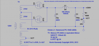
A competent PSU is a must, limited budget or not. Fortunately, a high performance PSU can be constructed at modest cost. "Full wave" voltage double the O/P of a Triad N-68X's single secondary, using 2X of this Schottky diode. Follow the doubler cap. stack with a LC reservoir section. Hammond's 156M seems to be a good fit for the filter choke requirement.
One fellow that contacted me has Tamura wound O/P "iron" salvaged from Sony R2R tape machines. Those not so lucky should (IMO) consider the Edcor GXSE5-5.5K for their builds.
Very recently, I've received requests from several members regarding the matter and starting a new thread seems appropriate.
The very tried and true cap. coupled voltage amplifier to SE "final" signal topology is employed.
A competent PSU is a must, limited budget or not. Fortunately, a high performance PSU can be constructed at modest cost. "Full wave" voltage double the O/P of a Triad N-68X's single secondary, using 2X of this Schottky diode. Follow the doubler cap. stack with a LC reservoir section. Hammond's 156M seems to be a good fit for the filter choke requirement.
One fellow that contacted me has Tamura wound O/P "iron" salvaged from Sony R2R tape machines. Those not so lucky should (IMO) consider the Edcor GXSE5-5.5K for their builds.
Attachments
Last edited:
I would try with the old R. Bates idea of cathode follower. Just to do something different.
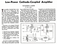
A Direct-Coupled Amplifier with Cathode Follower by Raymond H. Bates
Only two things:
1) There is a requirement for the OPT to have about 250R primary DC resistance which is not too bad for 5.5K primary impedance. Assuming the secondary DC resistance is about 0.35R (i.e. impacts on losses in the same measure) the overall efficiency would be 92%. Pretty good for budget amp.
2) some comments about sensitivity in the link above do not make sense to me as the voltage amp needs to deliver the full output voltage. Actually about 10% more because of the gain of the CF <1. So it should be good for normal use.
Hello Eli,
Thanks very much for starting the thread. I also appreciate you sending me a PM regarding the 6v6 se amplifier.
I’ll write more later when I get back home. I have used the sony (tamura) opts before with 45 and el84 and I can say they are very good. Im excited to build a nice 6v6 se for my altec 9844...
Thanks
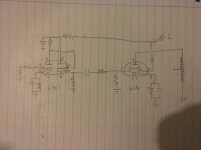
I bought a se 6v6 amp a while back and drew the schematic out by looking at the circuit. I doubled checked it for accuracy but I am old, retired and new to this stuff so it might not be accurate. I haven't drew the power supply yet.
These amps sound pretty good to me but maybe a little bit bass heavy.
These amps sound pretty good to me but maybe a little bit bass heavy.
Attachments
I bought another Sony RTR the other day that has the tamura output transformers in it. I hooked it up to my main system and it sounded real good. It uses 6bq5's.
45, I was looking at that direct coupled schematic two. The akai M series, Sony tc-500a and akai 1710 opt's have primary dcr around 400+. The stancor 3849 have around 250 dcr but there tiny trans and not common.
45, I was looking at that direct coupled schematic two. The akai M series, Sony tc-500a and akai 1710 opt's have primary dcr around 400+. The stancor 3849 have around 250 dcr but there tiny trans and not common.
Last edited:
Correction the Sony uses 6aq5's
The 6AQ5 is a member of the extensive 6V6 family. Except for screen grid fragility, the 6AQ5 can be viewed as a 6V6 in a 7 pin mini package.
FWIW, My guess is that Sony used full pentode mode and got approx. 5 W. out of the 6AQ5.
Member
Joined 2009
Paid Member
The 6AQ5 is a member of the extensive 6V6 family.
 never heard that claim before.
The remark that follows is excerpted directly from this datasheet.
"Within its maximum ratings, the performance of the 6AQ5 is equivalent to that of the 6V6-GT."
"Within its maximum ratings, the performance of the 6AQ5 is equivalent to that of the 6V6-GT."
Another Budget 6V6 SE Amp
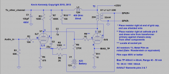
KevinKR has a great budget 6V6 SE Amp design on DIYAudio.com. See the thread "6V6 Behavior W/Fixed Bias (SE Amp)", post 80 to start with. Have built it myself for my daughter out of parts lying around and small Edcor transformers. Sounds great. Schematics from the thread below:
KevinKR has a great budget 6V6 SE Amp design on DIYAudio.com. See the thread "6V6 Behavior W/Fixed Bias (SE Amp)", post 80 to start with. Have built it myself for my daughter out of parts lying around and small Edcor transformers. Sounds great. Schematics from the thread below:
Attachments
SCD,
If the transformer is -1dB @ 40 Hz, it is -3dB @ 20 Hz (one pole response).
Yes it may saturate early at very low frequencies.
If the transformer is -1dB @ 18kHz, it is -3dB at perhaps about 24kHz (2 pole response).
For the price, that transformer seems to be pretty good.
And my old ear does not go above about 13kHz, and my loudspeakers do not go below about 35Hz.
But of course you could go for a more expensive, more heavy, and bigger transformer.
The major improvement would be more low frequency un-saturated power.
Ejam,
You can eliminate the signal current from the driver tube causing the 12V battery that is being charged and discharged with the signal alternations.
Connect the 12V battery in series with R9:
Connect the Negative end of the 12V battery to the left end of R9.
Connect the Positive end of the 12V battery to the top end of R8.
Then connect the bottom end of R8 directly to ground (the 12V battery was removed from there).
Then, as long as the signal is not so large as to cause grid current (grid current which causes clipping and bad sound), there is no current charging or discharging the 12V battery.
Just be sure to insulate the metal case of the battery from contacting the chassis (reduce the capacitance from the battery circuit to ground). I use double sticky tape to insulate the battery from the chassis (like the 3V, 6 V, and 9V batteries that I have used).
Last edited:
You can eliminate the signal current from the driver tube causing the 12V battery that is being charged and discharged with the signal alternations.
Obviously, it works, but I 'don't get it' with using a battery like this.
Those A23 batteries aren't rechargeable, are they?
How do they stand up in this kind of service?
What happens when the battery dies? Doesn't the tube lose bias and red-plate?
The Edcore GXSE5-5.5K is rated for 5 W. A triode wired 6V6 yields 2 W. The "iron" will go below 40 Hz., when passing 2 W. Also, keep the fact that a "standard" double bass' lowest note is 41 Hz. in mind.
Although I usually pair "peaking" the voltage amplifier with a GNFB loop, it can be tried by itself. For those not familiar with "peaking", it is making part of the total plate load inductive. As a consequence, the voltage amplifier's gain increases, as the frequency applied increases. Remember, XL = 2ΠFL and Z = (R2 + (XL)2)1/2. Getting the add with 1 hand ("peaking") and take away with the other ("iron" roll off) correct would be very tricky, but the "tweak" could be given a go.
Although I usually pair "peaking" the voltage amplifier with a GNFB loop, it can be tried by itself. For those not familiar with "peaking", it is making part of the total plate load inductive. As a consequence, the voltage amplifier's gain increases, as the frequency applied increases. Remember, XL = 2ΠFL and Z = (R2 + (XL)2)1/2. Getting the add with 1 hand ("peaking") and take away with the other ("iron" roll off) correct would be very tricky, but the "tweak" could be given a go.
VictoriaGuy,
The A23 is an alkaline battery. A fresh one should last as long as the date on the package or battery.
I used alkaline 3V and 6V batteries to bias input/driver tubes. I also used multiple 9V in series to bias 45 and 300B tubes. I used to check the battery voltages about once every 1/2 year, or year. Most of those amps had a meter that monitored the output tube current. I no longer employ battery bias.
Battery bias does not reduce the plate to cathode voltage (so you need a little less B+ voltage). Battery bias can have quite a range of plate current when changing from one tube to another tube. Notice that the schematic says the 6V6 current should be from 40mA to 50mA. Self bias would give a smaller current range from tube to tube than using battery bias.
Self bias does reduce the plate to cathode voltage, so you need a little more B+ (increase B+ by an amount equal to the bias voltage). Use a set of tube curves, load line, and calculate the self bias resistor. That gives reasonably consistent results, from tube to tube.
With the A23, there is very small current from the driver going through the 270k Ohm resistor. That current is there, even though you are not drawing grid current.
The other way to use it, as I proposed does work. It draws less current that way. The only significant current is if the signal is large enough to cause grid current.
Fixed (adjustable) bias needs a negative supply, and potentiometer. It needs to be adjusted to get the current in the tube that the design calls for. The current will reduce as the tube ages.
Fixed (non-adjustable) bias needs a negative supply. It will have a range of current that is not consistent from tube to tube (just like battery bias). The current will reduce as the tube ages.
Hello Eli and 6A3sUMMER: Thanks for the clarification on the output transformers. As others my age my hearing has diminished in the upper frequencies. My concern was in the lower range. I understand better now, the trade off seems reasonable. I think I have some telefunken OPTs from a old radio to play with for this project.
6A3-
Thanks for that battery info.
I like to think that things I build can be easily used by 'non-electronics' people, but that's not accurate, since I have built 'fixed' bias amps which do need a check on the voltage test points once in a while.
So battery bias probably isn't any 'worse' from a maintenance point of view.
BTW, I read that there's a big difference in performance between A23 batteries - they are just stacks of button cells held together by pressure (not welded), so a 'name brand' would be the best bet.
Make sure there's a bleeder in the HV B+ supply to protect the 'I'll just change the battery' folks.
- Status
- This old topic is closed. If you want to reopen this topic, contact a moderator using the "Report Post" button.
- Home
- Amplifiers
- Tubes / Valves
- Budget SE 6V6 Amp