And I am trying to get a grasp on what RL is supposed to represent, exactly. Per pages 571 & 572 of the Radiotron Designers Handbook, RL appears to be:
4*8*1900/8 which just evaluates to 7600.
This is supposed to be the full load across the primary but the manual goes on to clarify that only 1/4 this value is used for B operation, leaving the value to be 1900 which is the actual spec of the transformer.
I am assuming that I use 1900 ohms for the slope of my class B load line and 7600 ohms for the slope of the class A load line. Is this correct? This is a sextet of PPP el34 tubes in AB using a hammond 1650t for the output transformer.
Last edited:
First do the analysis for just a pair of tubes in Push-Pull.....
Once you get your Plate Load figured...you then divide by 3 to get the plate load for the 6 PPP tubes.....
What Class of operation are you shooting for ????
Load-Line for Push-Pull which you fit on the curve sheet and Plate Load are two different numbers by factor of 4 .....
Once I get more infoo..I can explain this in more depth..
If you read the radiotron (I have one of them from 1999), you can see that the optimum load for a pentode is equal to 90 to 100 of the DC resistance offered by the tube, say, divide the DC volts applied to the plate, and the DC milliamperes drawed by the tube, and this will be the AC plate resistance needed for the the tube. When using them in pushpull class A pure the autotransformer action of the primary will quad the impedance seen from each tube, so divide it by four to find optimal Plate to Plate load resistance.
Thank you for confirming this!If you read the radiotron (I have one of them from 1999), you can see that the optimum load for a pentode is equal to 90 to 100 of the DC resistance offered by the tube, say, divide the DC volts applied to the plate, and the DC milliamperes drawed by the tube, and this will be the AC plate resistance needed for the the tube. When using them in pushpull class A pure the autotransformer action of the primary will quad the impedance seen from each tube, so divide it by four to find optimal Plate to Plate load resistance.
Please take the data sheet of EL34 from Mullard and you find all info you need.
They speak about pair; you must divide by 3 the load listed there
Walter
They listed 5ka-a with 400VDC at the plate, so that puts the ppp el34 sextet at ~1670 ohms. That seems reasonable. I am going to run at 480VDC so the extra impedance at 1900 ohms might be necessary.
The whole 90 to 100 of DC resistance not valid...
Here is the info I have so far...
You have 6x EL34 tubes you want to run in PPP ....
You are running these tubes at 480V DC @ idle....
Keep in mind that there may be significant voltage dip at full power output...it is this drooped voltage that you design to, not the 480V idle voltage...
You would like to run in Class AB1 ...
What is the intended use ?? Hi-Fi or Musical Instrument ??
How are you feeding the screen supply ?? For Hi-Fi I recommend voltage regulation of the screen supply...
What kind of expected power level are you looking for ???
If you can answer these questions... I can show you step by step to select the optimum Plate-Load for your application..
To answer your original question about RDH-4 .... The equation for RL is mis-leading...... mainly because N1 is HALF the FULL number primary winding turns.... and it's term is squared in the brackets...
When discussing Push-Pull transformers, its best done from the perspective of full secondary turns to full primary tuns..... Then the 4 would not be next to R2 in that equation....
Last edited:
Transformers are specified end-to-end, even though we calculate the tube line end-to-B+.
When in doubt, read the data sheet. http://www.mif.pg.gda.pl/homepages/frank/sheets/129/e/EL34.pdf
We find a pair making 450V and 6.5k load, 40 Watts. To use six tubes, three pair, we use a load 1/3rd of the load for one pair. 2.3k is essentially 1.9k, no problem. The 120 Watts and 215mA are safe for the specified transformer.
Attachments
You can use the OT you have with 480 volts.
The spec from Philips/Mullard are for cathode bias, so you have to subtract the voltage drop in a resistors.
The max swing that you can obtain il less because the reflected Z is not optimal.
With 60 mA + 10 mA and 480-27 volt (resistors) each tube dissipate about 32 watt and it is a t the limit; you have to make a good choice on EL34. And this means you are in full class A close to the max power.
70 mA x 465 ohm ( without signal at input) = 31,5 volt, this is a bias point. (following the data sheet)
I suggest the fixed bias ; in this way the Z is always reasonable but you can set the Ibias at lower level and the 34 are working with less stress. p.e. 40mA ech one so you can stay in class A until 15 watt (+/-)
Walter
Problem with this data sheet, is they are not specifying the SCREEN VOLTAGE.....
Obviously "VB" is the main supply, and G2 is fed from there through Rg2.
RCA, and presumably Mullard or Philips, "interns" were very sharp people.
That´s not an "intern" job AT ALL.
The datasheet is the distillate of all knowledge about a tube, written by designers who were the sharpest brains handling both the theoretical problems, actual measurements, sampling and both Lab production and large scale Manufacturing.
And datasheets DO show Vg values (and everything else) , what else could they do?
So much so, that probably that´s not stated at *every* curve drawing but as a general note; something similar to "Vg=250V unless otherwise specified".
Interns in the old days generally started at the drawing desks, and similar "safe" jobs until they slowly got up to speed.
Mistakes in data sheets have made it to print over the years...
I personally know and knew RCA, GE, National Union engineers from that era... They assigned new engineers to shadow senior engineers and were given task to write up the application data sheets and plot the curves on the Tek 570 tracers....easy stuff but the kind of paper work senior engineers dreaded to do... Sometimes they had like 30 + tubes to have written up in a few weeks...so they were sometimes rushed to get the data out to market before other competitor companies...
I personally know and knew RCA, GE, National Union engineers from that era... They assigned new engineers to shadow senior engineers and were given task to write up the application data sheets and plot the curves on the Tek 570 tracers....easy stuff but the kind of paper work senior engineers dreaded to do... Sometimes they had like 30 + tubes to have written up in a few weeks...so they were sometimes rushed to get the data out to market before other competitor companies...
Yes that is my first intuition, but it doesn't line up with the actual observed current or voltage swing. I am making a mistake somewhere...but oddly, it's off by the same factor as that equation.The whole 90 to 100 of DC resistance not valid...
Here is the info I have so far...
You have 6x EL34 tubes you want to run in PPP ....
You are running these tubes at 480V DC @ idle....
Keep in mind that there may be significant voltage dip at full power output...it is this drooped voltage that you design to, not the 480V idle voltage...
You would like to run in Class AB1 ...
What is the intended use ?? Hi-Fi or Musical Instrument ??
How are you feeding the screen supply ?? For Hi-Fi I recommend voltage regulation of the screen supply...
What kind of expected power level are you looking for ???
If you can answer these questions... I can show you step by step to select the optimum Plate-Load for your application..
To answer your original question about RDH-4 .... The equation for RL is mis-leading...... mainly because N1 is HALF the FULL number primary winding turns.... and it's term is squared in the brackets...
When discussing Push-Pull transformers, its best done from the perspective of full secondary turns to full primary tuns..... Then the 4 would not be next to R2 in that equation....
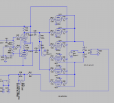
I uploaded the power amp section of the spice file but to directly answer your questions I am expecting between 100w to 150w RMS power.
-Musical instrument amplifier
-Fixed bias, I presume around -45 volts on the input grid
-Screen supply is from 1k resistor off B+, so 50mA*1000ohms = 50 volt drop, but I am unsure if the screens operate at this maximum draw in all conditions
I will probably have 200uf of capacitive filtering and 5Henry choke on a beefy power supply with solid state rectifiers. The power supply is 350-0-350. I am sure you're right about the sag but that is a bit ahead of what I can derive at the moment.
The output transformer in the sim has 64 henries on the primary, or 16H per coil on the primary. Since it's 1900:8 impedance ratio, it appears the inductance on the secondary should be .27Henries.
If each side of the power amp is only seeing a 1/4 of the 1900ohms during class B operation, then that is about an amp of current per side (480v/475ohms) so the way I am doing it doesn't add up. If I follow my interpretation of the Radiotron's guidance, it would be 480v/1900ohms which is about 250mA per side of tubes.
Transformers are specified end-to-end, even though we calculate the tube line end-to-B+.
When in doubt, read the data sheet. http://www.mif.pg.gda.pl/homepages/frank/sheets/129/e/EL34.pdf
We find a pair making 450V and 6.5k load, 40 Watts. To use six tubes, three pair, we use a load 1/3rd of the load for one pair. 2.3k is essentially 1.9k, no problem. The 120 Watts and 215mA are safe for the specified transformer.
Appreciate this.
Last edited:
OK....
Now I understand what your doing.....
Your 480V will typically wind up at 430V to 450V at clean full power and your screens will be around 400V..... I say this based on Typical available power transformers and that each screen will draw around 28mA at full power across a 1K ohm screen resistor...
For a pair of EL34 you looking at 3.4K .... for 6 Tubes in PPP ...you will be at 1K to 1.2K range... Figure about 150 Watts...... A 12AX7 driving from the plates is a bit weak of a driver for all those tubes, since your roughly have a driver output impedance of 38K into Miller Capacitance x3 ...
Last edited:
That 1k slope, does it represent a 4k primary impedance then? So if you added another pair it would make the impedance appear higher by that factor and so forth? So with 3 tubes per side and a 1900ohm a-a tx we'd have 475*3 as the apparent impedance? That would make sense...
That 1k slope, does it represent a 4k primary impedance then? So if you added another pair it would make the impedance appear higher by that factor and so forth? So with 3 tubes per side and a 1900ohm a-a tx we'd have 475*3 as the apparent impedance? That would make sense...
For the example given..... The "SLOPE" known as the "Load-Line" is 1k ohm... This represents a Primary impedance of 4k Ohms also known as the "Plate-Load" .... This is all for 2 tubes in PP.. If you have 4 Tubes in PPP then this becomes 2K primary load impedance ..... If we use 6 Tubes in PPP then the this becomes 1.3K Ohms Primary load impedance..
To be exact Class B amps have Plate-Load = 4x Load-Line....
Class AB amps have "most" of the cycle as 4x the Load-Line...
Class A Push-Pull does not see 1/4 Plate load in theory, because there is no AC current flow in the Center-Tap of the OT ....
This is only part of the story.... You need to make sure your inductance is adequate for your application.. -3dB freq POLE is when the XL = plate load....
With EL34 at your voltages...I believe 3.4k ohm is your starting point for 2 tubes PP...from doing similar load-lines for EL34....
Last edited:
- Status
- This old topic is closed. If you want to reopen this topic, contact a moderator using the "Report Post" button.
- Home
- Amplifiers
- Tubes / Valves
- Using a 1900ohm OT for 6 PPP AB el34