Just to be sure...
It's fine, however.....
TRY IT!! So it oscillates on the test-bench.... what harm happens?
With all respect to SY, it is more robust if the NFB does not share the same output damping resistor as the Outside World. In a Hi-Fi with 3-foot cables, it is probably no difference. Hang a 1,000 foot cable on there and there is considerable phase lag inside the audio band.
Yes, any amplifier will oscillate if layout is bad. I think you can wire this up tight and neat. One gotcha is the length of wires from the tube to the controls. As in many audio chores, you realy don't want long wires here.
I did try it - it makes no difference that I can see whether I wire it with/without the changes in the bypass caps and anode resistors, or whether I move the NFB inside or 'outside' the last stopper.It's fine, however.....
TRY IT!! So it oscillates on the test-bench.... what harm happens?
There seems to be a very small amount of oscillation consistently 'widening' the scope traces - but I'm not sure if that's important. The oscillation I had previously seems to have been eliminated with the 220pF across the NFB resistor. I have some pretty long wires (antennas..) attached to the circuit now - power wires up to the bench supply and the leads from the audio generator to the input. Scope leads shouldn't be much of a problem, but they are hooked up to input and output as well. Question: Right now I just have the scope attached across the output.
Should I be loading the output with a resistor to mimic the input stage of a (tube) power amp?
Last edited:
No, I don't. There is no way to be sure that with a high gain stage plus 2 voltage followers there aren't some frequency at the gain is 1 or more and multiple of 360°. So it is better to avoid it.Yes. So can you.
Quick update-
It's still on the breadboard but doesn't seem to have much bass getting through, even with the pot at full 'bass end' rotation. Anything below 200 Hz is half (-6 dB?) or worse
Lots of treble though - double the input voltage at the output (6 dB?).
I'll check the wiring again tomorrow.
I don't really understand how the tilt circuit works, so I have problems troubleshooting it.
And, it may be an amplifier problem and nothing to do with the tilt control at all, I suppose.
Please, I don't want to be pejorative, that's not my intention; but do you know to bias a tube from the data sheet? There you can choose the best biasing point. I suggest to read anywhere in the web how to do it, and choose your best operating point, and forget led's, because excepting rare casualty, this element will not give the best bias for the tube. Also, they introduce noise in the circuit.
No offense taken.Please, I don't want to be pejorative, that's not my intention; but do you know to bias a tube from the data sheet? There you can choose the best biasing point. I suggest to read anywhere in the web how to do it, and choose your best operating point, and forget led's, because excepting rare casualty, this element will not give the best bias for the tube. Also, they introduce noise in the circuit.
Can you explain how a different bias point will affect the frequency response?
That's the problem I'm now having with this circuit.
It sounds like you only build circuits you design completely yourself?
I'm a beginner so I mostly build things from circuits that other people have designed.
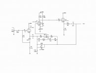
In this circuit, I don't have a clear understanding on how the NFB and the 'tilt' tone filters interact.
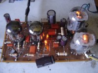
I understand the concerns with noise and oscillation, which are certainly worse on a spread-out layout on a 'breadboard' (real board with terminal strips, not a plastic 'breadboard' with holes for wires). However, that's mostly under control for now.
I don't want to move to a final, 'tight' wiring scheme around the tube socket (which will help to control oscillation/noise, I'd hope) unless/until I get the circuit working with appropriate frequency response and gain.
No offense taken.
Can you explain how a different bias point will affect the frequency response?
That's the problem I'm now having with this circuit.
It sounds like you only build circuits you design completely yourself?
Yes, because I'm engineer, and generally Engineers design circuits, their own circuits, and sometimes this circuits become popular, other are saved under 7 keys as a top secret. For example, the circuit of a PC motherboard or a cell phone.
We had been qualified at universities with lots of mathematics several years (9 in my case) do such a job. But I also search everywhere for circuits already designed by others, for example, old magazines, books and patents.
We already had beginner, no one was born being a genius. Also meI'm a beginner so I mostly build things from circuits that other people have designed.
In this circuit, I don't have a clear understanding on how the NFB and the 'tilt' tone filters interact.
") This is a necessary step: the first is the most important.
This is a necessary step: the first is the most important.
Usually a bad bias not conduct a circuit to have bad frequency response, moreover to generate some kinds of distortion, but incorrect bias can cause, for example, grid bias current which in turns makes the input impedance of a tube low, causing indirect bad frequency response. Breadboarding, don't worry, at audio frequencies it isn't too important as a way to testing a circuit.I understand the concerns with noise and oscillation, which are certainly worse on a spread-out layout on a 'breadboard' (real board with terminal strips, not a plastic 'breadboard' with holes for wires). However, that's mostly under control for now.
I don't want to move to a final, 'tight' wiring scheme around the tube socket (which will help to control oscillation/noise, I'd hope) unless/until I get the circuit working with appropriate frequency response and gain.
I also make my own breadboards, although in other fashion.
Attachments
Changing C6 - the coupling cap after the first tube section - seems to have brought the bass response up. I had to use an electrolytic there - there's about 160 volts across that cap, so a 10uF film cap is out of the question.
I checked the bias across the LEDs - 1.9 volts each.
For the first tube section - this seems about right to handle the 2 v signal from a CD player?
I checked the bias across the LEDs - 1.9 volts each.
For the first tube section - this seems about right to handle the 2 v signal from a CD player?
I checked the bias across the LEDs - 1.9 volts each.
For the first tube section - this seems about right to handle the 2 v signal from a CD player?
2V RMS or peak?
2V RMS or peak?
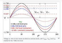
'Line level' is pretty confusing for me, but I'm assuming that the peaks will be less than +/- 1.9V so 1.9 volt bias should prevent clipping.
I think 'consumer level' is about 1.4 v peak?
From wiki: Line level - Wikipedia
Attachments
I usually accept line level to be 1VRMS over 47/50KΩ. In any case the bias seems to be a little high, but not the responsible for the poor bass response.
What is this devices feeding? Say, what follows it in the link to the speaker? Perhaps, the ohmic load is low and the last capacitor (3.3 µF) is too low for that load. Also, is this device surely the guilty of poor bass?
What is this devices feeding? Say, what follows it in the link to the speaker? Perhaps, the ohmic load is low and the last capacitor (3.3 µF) is too low for that load. Also, is this device surely the guilty of poor bass?
I didn't get any response to this question; I don't think there are many readers of this thread.Question: Right now I just have the scope attached across the output.
Should I be loading the output with a resistor to mimic the input stage of a (tube) power amp?
The bass response is measured, not depending on my ears or speakers.What is this devices feeding? Say, what follows it in the link to the speaker? Perhaps, the ohmic load is low and the last capacitor (3.3 µF) is too low for that load. Also, is this device surely the guilty of poor bass?
The 6M11 preamp is on my electronics bench.
Input is mostly sine wave from HP 339A with viewing input/output on 'scope with probes connected to input and output.
Sometimes I feed music from CD player to input and output is sent to solid state 'shop' receiver and 'shop' speaker...with scope probes left in place.
Usual tube amps has input impedance around 500KΩ excepting some particular designs.
As you have an oscilloscope, and a signal generator, then make as follows:
1.- Put the signal generator in the range of 1KHz and 1VRMS or peak. In this case it is indifferent.
2.- The scope at the output end of the above mentioned capacitor without the tip attenuator, or with a 1MΩ as a load for the amp. Oscilloscopes without input attenuator, has usual 1MΩ resistance plus 30pF that don't care at this frequency. Take the reading of the output voltage (Peak or RMS) and remember this.
3.- Decrease slowly the frequency of the generator until the output is 70.7% of the above reading; say, taking the input level constant and taking the same RMS or peak values.
4.- Let us know the frequency at which the output signal has decreased to 70.7% or √2/2 times, simultaneously the phase ought to rotate 45 electrical degrees. Keep the tone control centered, or still better, remove the passive elements connected to the center pin, leaving it at flat response.
This will became the lower frequency the amp can "amplify", this isn't a certainty, but a convention. This overcomes the "I believe" or "It seems" from the previous sentences.
Good luck.
I'll try those things - the ones I understand- and report back.
a)The whole point of the preamp/linestage is to act as a tone control with no gain. I want to see lots of bass boost at one end of the pot rotation, and corresponding treble boost at the other end. I'm not sure what the mid-point of the circuit is - what frequency will be unaffected by pot rotation, so that needs some experimentation.
b)'Removing the passive elements attached to the pot wiper' - I don't understand what this means.. The pot and the tone/tilt control are interacting with the NFB in a way I don't understand- it's not simple to try to 'bypass' parts of the tone control. c)Also, I don't understand the 45 deg phase rotation idea, at all - don't I have to use Lissajous (X-Y) patterns to determine this? d)'tip attenuator' in the probe - do you mean to use a 1X probe not the 10x I'm using?
- Status
- This old topic is closed. If you want to reopen this topic, contact a moderator using the "Report Post" button.
- Home
- Amplifiers
- Tubes / Valves
- 6M11 Compactron Preamp with Tilt Tone Control