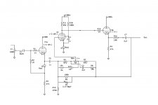
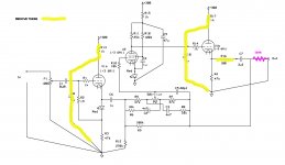
I've been playing with a preamp/linestage circuit from Stuart Yaniger (SY) that uses one 6M11 Compactron tube for each channel.
See attached schematic.
I was attracted to this design because:
a)it incorporates a tilt tone control, which I've never used
b)it uses a 6M11 compactron tube, which is also new to me.
I've 'breadboarded' one channel and it seems to be working OK, so I'm thinking about the layout and components I'll use when I build it into a chassis.
(Note- things get cramped around that 12-pin socket).
Questions about capacitors:
There are some caps that connect the (300volt range) plate circuits to ground.
C9 is a 47uF cap, so that one has to be an electrolytic 350 volts or more
C8 and C10 are 1uF - electrolytics will be OK there also?
C7 is the output coupling cap 3.3 uF - what type should I use in that location?
BTW, possibly because the breadboard layout was a bit spread out, I had some oscillation problems. Those were cured with a 220pF cap around the 100k R9. Comments?
Thanks!
I'm sure I'll have more questions later, including good sources for 2-gang linear pots.
Attachments
Following with interest. I just picked up a suitcase full of tubes, among them a lot of triple triode 6_11 Compactrons. I remember back in the day that it was mostly GE TVs that used Compactrons, and we generally considered GE to be crap so we ignored them. They are dirt cheap, hopefully you have good results.
Definitely more than the usual 'advance planning' on the point-to-point wiring around the socket is required!
It gets crowded, fast - 12 pins, 2 triodes and a pentode in the 6M11.
I may use turrets, arranged in a ring outside the socket, for a start.
More pencil and paper work before the drill press gets started.....
It gets crowded, fast - 12 pins, 2 triodes and a pentode in the 6M11.
I may use turrets, arranged in a ring outside the socket, for a start.
More pencil and paper work before the drill press gets started.....
> 'advance planning' on the point-to-point wiring around the socket is required!
Ampeg did about that with the compactron trip-triode.
https://el34world.com/charts/Schematics/files/Ampeg/Ampegv4_v22.service_manual.pdf
https://el34world.com/charts/Schematics/files/Ampeg/Ampeg_v4_vt22.pdf
Ampeg did about that with the compactron trip-triode.
https://el34world.com/charts/Schematics/files/Ampeg/Ampegv4_v22.service_manual.pdf
https://el34world.com/charts/Schematics/files/Ampeg/Ampeg_v4_vt22.pdf
A G2 stopper would help stability some, but probably more important would be a cathode stopper from the first cathode follower. These are so often overlooked that cathode followers have gotten an undeserved bad reputation. It, and a somewhat more conservative (maybe a K Ohm or so) stopper on the second cathode follower, need to be mounted just like a grid stopper - right next to the pins.
I won't comment about the circuit's complexity without the politeness screen of an emoji.
All good fortune,
Chris
I won't comment about the circuit's complexity without the politeness screen of an emoji.
All good fortune,
Chris
Yes, and that PCB was hand-drawn, not organized by computer software???Ampeg did about that with the compactron trip-triode.
I'm sorry about my clarity. I try my best but it's hard to judge a stranger's level of experience in an arcane subject while typing (not my strong suit) at a glowing screen. At least we're both native English speakers, which improves subtext and humour. But, we colonials struggle on for Queen and Country. Hear, hear.Thanks, but...
As usual I don't understand...
How can I put 'stoppers' on the cathodes without messing up the (LED) bias?
You seem to be talking about a 10k and a 1k stopper between the LED and the pin?
Cathode followers need a damper between themselves and external reactive, especially capacitive, loads. My ham radio days are a half century away, but there is some proper name brand kind of RF oscillator that works that way. To keep the oscillator from working so well the damping resistor just needs to be in series between the cathode and the capacitive load. It could even replace the LED bias diode, taking signal from it's "bottom" end.
Things like this fall into the category of "lore". They're true, but often can be ignored. A fly-wired breadboard build has lots of other knowable issues that can just as easily contribute to instability. So my comments are intended more for background and preparation than calls to arms.
Always the best,
Chris
Here's a simpler version:I won't comment about the circuit's complexity without the politeness screen of an emoji.
Attachments
Looks the same to me, but then again, I didn't understand all the B+ and small capacitor stuff anyway. Big fan of anode followers, not of pentodes (except Bohmblau's), can't see a reason for the second cathode follower. Just one guy's opinion; no better than anybody else's.Here's a simpler version:
All good fortune,
Chris
So for a stereo preamp, it would be better to 'switch sides' to the other tube?
Robert Weaver built a low-power push-pull amp (with tone control) with the 6M11.
6M11 push-pull spud amp
Mini-Tube Audio Amplifier - Part 1
Robert Weaver built a low-power push-pull amp (with tone control) with the 6M11.
6M11 push-pull spud amp
Mini-Tube Audio Amplifier - Part 1
Yes, and that PCB was hand-drawn, not organized by computer software???
Hand-taped, most likely. A pencil sketch, a big sheet of Mylar, pinstripe tape. Perhaps done oversize and then shot-down to a negative.
...a cathode stopper from the first cathode follower....
The first CF does not drive much reactance. The tone-caps are beyond dozen-K resistors. Yes, without knowing what lies Beyond, the output CF should have a stopper (~500r), and the NFB should be inside the stopper.
It is not a good idea to use the 3 sections inside a single tube to process the same signal, you can get strong oscillations regardless grid and screen stoppers.
Three GAIN stages, yes, begging for trouble. But this is two unity-gain stages, so just one gain stage. The Ampeg tone-amp is more brave. I can criticize these for heavy heater hum and very bold working of the power bottles, and now short supply of these Compactrons, but they did serve very well and no squirreliness in the tonestack.
Yes, without knowing what lies Beyond, the output CF should have a stopper (~500r), and the NFB should be inside the stopper.
You mean to add a 500R after the 100R, like this:
Attachments
I'd appreciate thoughts on cap (type, not boutique vs ordinary) selection.
Thanks!
Thanks!
Questions about capacitors:
There are some caps that connect the (300volt range) plate circuits to ground.
C9 is a 47uF cap, so that one has to be an electrolytic 350 volts or more
C8 and C10 are 1uF - electrolytics will be OK there also?
C7 is the output coupling cap 3.3 uF - what type should I use in that location?
Thanks, Chris, and PRR, and others... I didn't understand the suggestion from PRR, since there was/is already a 100R stopper on the output tube cathode. Perhaps the idea was to increase the stopper value to 500R? I also didn't understand the 'NFB inside the stopper' recommendation That's why I posted the modified schematic, in the hope that I'd get corrections.I'd really recommend that cathode stoppers be mounted right at the valves's sockets, just as you'd do at any other element, and for the same reasons. Chris
I'm still interested in opinions on the caps - especially the output caps. Electrolytic? NonPolar electrolytic? Film?
...Can you be sure... oscillator?
Yes. So can you.
Attachments
Yes. So can you.
Just to be sure before I modify my circuit...

PRR: the changes you marked will NOT make an oscillator, correct??
Or were you showing Osvaldo the path to encourage oscillation (by removing the separate anode resistors and bypass caps??
With my level of ignorance, subtle hints aren't always the best!!
Attachments
Last edited:
- Status
- This old topic is closed. If you want to reopen this topic, contact a moderator using the "Report Post" button.
- Home
- Amplifiers
- Tubes / Valves
- 6M11 Compactron Preamp with Tilt Tone Control