I’m building a little proto board with some 10M45S CCS regulators that I can use to quickly build circuits for evaluation. I’ve not worked with proto board much and my technique is not very polished. I looked in MJ Building Valve Amplifiers and found a photo of some dodgy work he uses to illustrate bad techniques. One of the things he comments on are wires going across the board diagonally. Is that really such a sin?
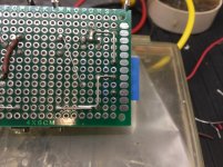
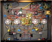
The photo below shows one I just finished. The half you can’t really see with the brown wire is my usual disorganized work I’m not really that eager to share") The part I photographed is my absolute best effort. I’d like to do something similar that would become a permanent finished product for a project rather than a just prototype.
The part I photographed is my absolute best effort. I’d like to do something similar that would become a permanent finished product for a project rather than a just prototype.
Please offer a critique and a few specific suggestions. Brutal honesty works just fine.
1) You can see the diagonal jumper. Is that really so bad?
2) You can see where I squared out the traces. That took some effort. I hope MJ would be pleased, but is that really better? Is it acceptable technique to simply bridge the nodes with solder and skip the wire?
3) I’m a bit reluctant to loop wire around the center pin of the TO220 part for clearance reasons. I brought a trace next to it and attempted to get a wire to bridge that gap to the trace; that was an abject failure. I ended up using a bunch of solder to bridge the gap. I’m sure there is a better way. I was tempted to solder and then bend the remaining lead over to the trace. Any cool tricks you can suggest for that?
The photo below shows one I just finished. The half you can’t really see with the brown wire is my usual disorganized work I’m not really that eager to share
The part I photographed is my absolute best effort. I’d like to do something similar that would become a permanent finished product for a project rather than a just prototype. Please offer a critique and a few specific suggestions. Brutal honesty works just fine.
1) You can see the diagonal jumper. Is that really so bad?
2) You can see where I squared out the traces. That took some effort. I hope MJ would be pleased, but is that really better? Is it acceptable technique to simply bridge the nodes with solder and skip the wire?
3) I’m a bit reluctant to loop wire around the center pin of the TO220 part for clearance reasons. I brought a trace next to it and attempted to get a wire to bridge that gap to the trace; that was an abject failure. I ended up using a bunch of solder to bridge the gap. I’m sure there is a better way. I was tempted to solder and then bend the remaining lead over to the trace. Any cool tricks you can suggest for that?
Attachments
1) You can see the diagonal jumper.
2) You can see where I squared out the traces.
3) I’m a bit reluctant to loop wire around the center pin of the TO220.
Jumpers are fine as long as they don't short, but you can use insulation on them.
Squaring off wires is fine, just not for a sensitive circuit node. Keep that compact.
TO-220 or even TO-92 can use a triangular pattern, bend out the center leg.
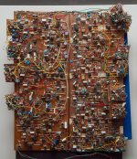
Maybe this board built by the great analog guru Jim Williams will be some inspiration.
https://images.computerhistory.org/blog-media/jim-williams-circuit.jpg
Last edited:
Bend out the center leg. And the Jim Williams board IS an inspiration.
The TO-92 is really bad for protos, so bend the center leg out.
But only once, they break off easily.
Only experts who know what they're doing can get away with
what looks like junk to some.
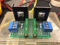
Perf board for more complex prototyping, say more than a half dozen parts. Easier to shape and cut, easier to locate components, easier to guarantee two traces don't accidentally touch, easier to mount the board, but a little harder to solder.
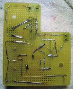
It was an odd shape because of where it needed to fit:
It was an odd shape because of where it needed to fit:
Attachments
Last edited:
I looked in MJ Building Valve Amplifiers and found a photo of some dodgy work he uses to illustrate bad techniques. One of the things he comments on are wires going across the board diagonally. Is that really such a sin?
IMHO Morgan Jones tells how to do the "real engineering", both on developing circuits as well as how to build them. In a world full of audiophoolery that is very welcome! But if you feel comfortable with alternatives, go for it!
I don't like to bend out the centre pin right at the package. This can lead to pin breakage. I like to bend the pins some distance away from the package.
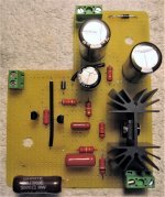
This point actually touches on what I think is really the key variable in making neat proto board: spending some time and giving consideration to spacing and orienting the active components on the board. If you spend time on this you can populate the Rc's and C's with minimal jumpering.
This point actually touches on what I think is really the key variable in making neat proto board: spending some time and giving consideration to spacing and orienting the active components on the board. If you spend time on this you can populate the Rc's and C's with minimal jumpering.
- Status
- This old topic is closed. If you want to reopen this topic, contact a moderator using the "Report Post" button.
- Home
- Amplifiers
- Tubes / Valves
- Help with proto board techniques