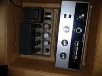
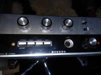
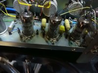
ok, i have inherited the above amp from grangfather, and its all merky waters to me..i shall post pics of the units and all seems complete including the three rare 807 valves .
so this has been packaged away for at least twenty years so will be treading carefully, have a look at the pics i upload and give me opinions on what i should swap out or check and how to go about trying the thing out ?
so this has been packaged away for at least twenty years so will be treading carefully, have a look at the pics i upload and give me opinions on what i should swap out or check and how to go about trying the thing out ?
Attachments
-
 IMG_20190218_001720.jpg452.8 KB · Views: 302
 -
 IMG_20190218_001726.jpg467.6 KB · Views: 333
 -
 IMG_20190218_001644.jpg574.1 KB · Views: 301
 -
 IMG_20190218_001619.jpg557.1 KB · Views: 309
 -
 IMG_20190218_001515.jpg358.8 KB · Views: 314
 -
 IMG_20190218_001101.jpg631.1 KB · Views: 140
 -
 IMG_20190218_001023.jpg532.2 KB · Views: 112
 -
 IMG_20190218_001043.jpg419.6 KB · Views: 117
 -
 IMG_20190218_001001.jpg667.5 KB · Views: 115
 -
 IMG_20190218_001132.jpg620.1 KB · Views: 129
It is a matter of routine to replace all electrolytic capacitors in these "vintage" units. Electrolytic caps. literally dry out over time.
Carbon composition resistors should be checked for drift in value and for noise.
There's a big difference between the 807 (a beam power tetrode) and the ECC807 (a twin triode).
The schematic for the preamp is here and the schematic for the power amp is here. The 6GW8/ECL86 is scarce. Scan the archives for conversion to PCL86 discussions.
If one want's to be future-proof a slight rebuild could be done :It is a matter of routine to replace all electrolytic capacitors in these "vintage" units. Electrolytic caps. literally dry out over time.
Carbon composition resistors should be checked for drift in value and for noise.
There's a big difference between the 807 (a beam power tetrode) and the ECC807 (a twin triode).
The schematic for the preamp is here and the schematic for the power amp is here. The 6GW8/ECL86 is scarce. Scan the archives for conversion to PCL86 discussions.
Add a ECC83/12AX7 and connect as the triodes
repin the power tube sockets to EL84.
More information on the Rogers Cadet III is to be found on this radiomuseum page:
Cadet III Ampl/Mixer Rogers, Catford see also Rogers Birming
When I renovated the Cadet III's big brother the HG88 III, I replaced all the electrolytic capacitors and the solid state rectifiers. Besides cleaning the valve pins and bases with isopropyl alcohol and squirting some contact cleaner in the pots, that was all that was required to make the amplifier sing like new!
The three ECC807 valves in the control unit are as rare as hen's teeth. Some NOS are still to be found, but are very expensive as per this auction listing:
BRIMAR ECC807 RARE BRITISH VINTAGE NEW OLD STOCK NEW IN BOX TESTED VALVE TUBE | eBay
The four ECL86 valves are not as rare and NOS can be obtained from Watford Valves:
Watford Valves product search :: ecl86
Don't know if you've been tempted to power up the Cadet yet, Crusher. As the amp has been in storage for 20 years you should proceed with caution.
Some good 'how to power up' information is available on the site below (although it's not likely you will have access to a tube tester!) Please read before continuing:
How to Power Up a Tube Amp After a Long Time In Storage | Warehouse Guitar Speakers
Some good 'how to power up' information is available on the site below (although it's not likely you will have access to a tube tester!) Please read before continuing:
How to Power Up a Tube Amp After a Long Time In Storage | Warehouse Guitar Speakers
The Rogers Cadet III and HG88 III were the last of the golden era of valve amplifiers and used the latest technology in tubes as represented by the ECC807.ECC807 !!!! . . . why this choice ?
Due to the advent of solid state amplification, the brave new world of tubes such as the ECC807 did not last long, hence the scarcity of these devices.
ECC 807, Tube ECC807; Rohre ECC 807 ID18593, Double Triode
There's lots of information to be found on this forum and elsewhere with regard to modifying the Cadet III to take different valves types.
However, I would like to make the point that the manufacturing quality of the original Brimar and Mullard valves fitted to the amp was of the highest order. If only all modern valves could match their standard of reliabiity!
Consequenly, it is probable that Crusher's valves, particularly the rare ECC807 preamp valves, are still working fine. My 50 year old HG88 III is still running on its original Brimar and Mullard valve complement. Let's wait and see how the original valves work before talking about modifications.
If one want's to be future-proof a slight rebuild could be done :
Add a ECC83/12AX7 and connect as the triodes
repin the power tube sockets to EL84.
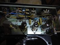
I agree with the thinking and have made similar suggestions in the past. Unfortunately, the power amp schematic suggests that only 2X Noval sockets are present on that chassis.
 BTW, pentode mode "finals" are OK, provided the EL84/6BQ5s are operated conservatively.
Perhaps the OP can post power amp photos too. If space can be found on that chassis for an additional Noval (9 pin mini) socket, a 12AX7/ECC83 could be used for the voltage amplifiers and DN2540N3-G MOSFETs employed as the "concertina" phase splitters.
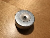
FWIW, the preamp schematic seems to imply a ceramic cartridge in the phono setup.
The Cadet III came with a choice of silver (ceramic) and gold (moving magnet) plug in modules.FWIW, the preamp schematic seems to imply a ceramic cartridge in the phono setup.
These plug into the 'Disc Adaptor Socket' labelled SK3 on the preamp schematic.
Crusher, do you have these little cylindrical, multi-pin plug in modules?
Hi crusher007,
Nice.
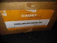
If you want to retain the value of the amplifier, see how much they make on ebay, please do not modify it. Keep it as original as possible. The packaging all adds to the value, so keep all that too.
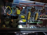
You are fortunate, the mk III has more robust output transformers than the 'all in one' later version and sounds a little better IMO. ECL86s are not that difficult to come by. The ECC807 is hard to find, but have an easy time so will most likely be fine.
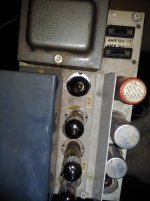
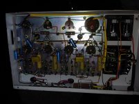
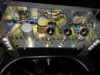
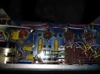
The coupling caps (the yellow and mustard coloured ones) are Philips and Mullard and have an excellent reputation and unlikely to need replacement.
The small blue electrolytics will quite possibly need changing.
The can caps might just re-form if you take care powering it up.
Do not plug it in until you make a 'dim bulb tester'. Google it.
When ever you switch on make sure you have speakers or dummy loads fitted.
Then with the bulb tester in circuit watch that the bulb dims soon after power on. If it does not dim there is a fault, switch off and investigate.
If it does dim, give it 60 seconds and switch off. Leave it 5 minutes. Next put your meter on the HT (B+) line and switch on again for a couple of minutes this time. Note the highest HT voltage. Touch each of the can capacitors and check they are not getting warm or worse hot. Check for any bad smells or hot smelling components.
If all is well switch on again and leave it on 15 minutes. Watch the HT voltage and check the caps for temperature etc. If the HT has increased since the last reading, repeat until the HT stays the same. It might take an hour or more, just make sure the cans do not warm up more than the chassis. Then switch off and leave it an hour or so.
Next time remove the bulb tester and switch on for 60 seconds, then switch off. Wait 5 minutes. This time when you switch on and if all is well you should get HT at full specification and little (or no) hum or buzz from the speakers.
If you get any of the cans warm up or loud hum, you will have to replace the can caps...
Alan
Nice.
If you want to retain the value of the amplifier, see how much they make on ebay, please do not modify it. Keep it as original as possible. The packaging all adds to the value, so keep all that too.
You are fortunate, the mk III has more robust output transformers than the 'all in one' later version and sounds a little better IMO. ECL86s are not that difficult to come by. The ECC807 is hard to find, but have an easy time so will most likely be fine.
The coupling caps (the yellow and mustard coloured ones) are Philips and Mullard and have an excellent reputation and unlikely to need replacement.
The small blue electrolytics will quite possibly need changing.
The can caps might just re-form if you take care powering it up.
Do not plug it in until you make a 'dim bulb tester'. Google it.
When ever you switch on make sure you have speakers or dummy loads fitted.
Then with the bulb tester in circuit watch that the bulb dims soon after power on. If it does not dim there is a fault, switch off and investigate.
If it does dim, give it 60 seconds and switch off. Leave it 5 minutes. Next put your meter on the HT (B+) line and switch on again for a couple of minutes this time. Note the highest HT voltage. Touch each of the can capacitors and check they are not getting warm or worse hot. Check for any bad smells or hot smelling components.
If all is well switch on again and leave it on 15 minutes. Watch the HT voltage and check the caps for temperature etc. If the HT has increased since the last reading, repeat until the HT stays the same. It might take an hour or more, just make sure the cans do not warm up more than the chassis. Then switch off and leave it an hour or so.
Next time remove the bulb tester and switch on for 60 seconds, then switch off. Wait 5 minutes. This time when you switch on and if all is well you should get HT at full specification and little (or no) hum or buzz from the speakers.
If you get any of the cans warm up or loud hum, you will have to replace the can caps...
Alan
ok guys, big thanks to all of you lads for the input,this is going to be fun.
i will power up as instructed and i do possess the inline bulb jobby to assist as directed, so gonna try this later and will report the findings asap.
i would like to keep it original to be honest initially and see how the tubes look when fired up , if tubes are not good then we can always look at amending but would like to keep it as is if possible.
i think i am defo gonna replace the blue caps as according to advice received these seem to be the danger area , what would be the best caps to replace with and where from? and i have read something about ripple ratings being particularly critical on these or am i on the wrong path?
if any one needs any further pics of any of it to help me sort things out i will gladly assist and thanks all and do please keep the advice coming as i will need some help to get this beauty running clean again
... i will power up as instructed and i do possess the inline bulb jobby to assist as directed, so gonna try this later and will report the findings asap.
i would like to keep it original to be honest initially and see how the tubes look when fired up , if tubes are not good then we can always look at amending but would like to keep it as is if possible.
Good start.
... i think i am defo gonna replace the blue caps as according to advice received these seem to be the danger area , what would be the best caps to replace with and where from? and i have read something about ripple ratings being particularly critical on these or am i on the wrong path?
The blue caps are all cathode bypass caps so do not need high ripple ratings.
(The high ripple cap will be the one(s) just after the rectifier.)
To keep the look, use axial types. Most originals are 40uF 16 volt, so go with 47uF 25 volt replacements. (These Vishays are blue too: https://uk.farnell.com/vishay/mal203036479e3/cap-47-f-25v/dp/1165421) I think you need 8, 4 in the amp and 4 in the pre-amp.
The other cap in the pre is 100uF 4 volts. Go with 100uF 10 volts. (Like this https://uk.farnell.com/vishay/mal203034101e3/cap-100-f-10v/dp/1165408) You need 2.
If you have not found the circuit and component values yet they are all here. Rogers RD Cadet MK 3 Stereo Amplifier Circuit Diagram and Operating Manual | valve-radio.co.uk
Alan
Let's wait and see how the original valves work before talking about modifications.
High μ/high RP types, like the ECC807, run at approx. a 900 μA. plate current. That low current equates to a long service life. There's good reason to believe those tubes will be fine. Brimar ran a 1st rate operation.

OTOH, even well made power O/P tubes wear out in fairly short order.
 Switching from scarce ECL86s to not nearly as scarce PCL86s involves only dealing with a heater supply issue.
 - Status
- This old topic is closed. If you want to reopen this topic, contact a moderator using the "Report Post" button.
- Home
- Amplifiers
- Tubes / Valves
- Rogers Cadet MkIII pre and power amp adventure