Wow, we have a new Guru!


On another note- this thread lit a fire under me. Time to dig out a few clear-top 6FQ7's and build a mu follower. I need to build a crossover and baffle step compensation preamp anyway. Maybe I'll use a 6N1P or 6DJ8 as the top tube?
Last edited:
On another note- this thread lit a fire under me. Time to dig out a few clear-top 6FQ7's and build a mu follower. I need to build a crossover and baffle step compensation preamp anyway. Maybe I'll use a 6N1P or 6DJ8 as the top tube?
Use MOSFET - based Gyrator, like I do. Let Gurus hiss and spit.
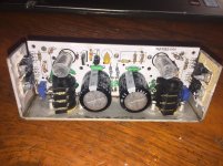
Here is my Preamp+ PCB, with Gyrator load of the triode, CCS load of cathode follower, and relay shunting of outputs.
Attachments
Strange for a poster with no originality to display!
Or queries??
He reminds me one more personage, I would not say his name. Everything that he can not understand is bad.
Default Search shews no threads started by N101N
Strange for a poster with no originality to display!
Or queries??
This seems like a start of a Personal Attack.
Don't go there.
Also: thread start count may not be a valid metric. Some otherwise brilliant people can't find the New Thread button. Some don't feel a need to start a thread for every good thought, but weave them into existing threads.
The mu follower is basically a common cathode amplifier
It is definitely not. It is a compound with new and fundamentally different properties and behavior.
increased the dynamic load resistance perceived by the lower device, which as you are no doubt aware will greatly increase linearity and gain.
On the contrary, distortion will greatly increase, but it is not simply a matter of increased impedance, there is much more to it.
I'm not even a huge user of the mu follower, but it's a great single ended (yes, this is not a blanced, or push-pull type of stage!) circuit
Did Morgan Jones say so? But no, the signal is balanced (not referred) to ground.
There is no "balanced action, and the harmonic content is very similar to a common cathode that is loaded with an equivalently selected load to the reflected resistance shown by the cathode follower and load resistor.
The harmonic content is very dissimilar to a common cathode, only odd harmonics being produced as one of many negative consequences of the balanced state.
Morgan Jones' book has obviously not helped you towards a better understanding of the present topic, which proves to be too elusive to treat for that genre of authors.
Many amplifiers proudly announced to be single ended are actually out-and-out balanced. Most people have bad taste, poor ability to judge sound quality and perceive the single ended sonic character as a nuisance. A "clean" sound is more widely preferred, that is to say, when a small portion of the input signal is transferred. It is efficiently accomplished by designing amplifiers as a voltage regulator / oscillator consisting of various balanced stages and techniques imported from the industrial sphere.
I do use the push-pull topology, but I don`t call it single ended or low distortion.
Everything that he can not understand is bad.
Tell us what you understand.
"It is efficiently accomplished by designing amplifiers as a voltage regulator / oscillator consisting of various balanced stages and techniques imported from the industrial sphere" Eh! Sorry, you've lost me there.
The OP seems to have resolved his issue, think everyone's just arguing about semantics now.
Andy.
The OP seems to have resolved his issue, think everyone's just arguing about semantics now.
Andy.
It is definitely not. It is a compound with new and fundamentally different properties and behavior.
On the contrary, distortion will greatly increase, but it is not simply a matter of increased impedance, there is much more to it.
Did Morgan Jones say so? But no, the signal is balanced (not referred) to ground.
The harmonic content is very dissimilar to a common cathode, only odd harmonics being produced as one of many negative consequences of the balanced state.
Morgan Jones' book has obviously not helped you towards a better understanding of the present topic, which proves to be too elusive to treat for that genre of authors.
Many amplifiers proudly announced to be single ended are actually out-and-out balanced. Most people have bad taste, poor ability to judge sound quality and perceive the single ended sonic character as a nuisance. A "clean" sound is more widely preferred, that is to say, when a small portion of the input signal is transferred.
If you believe that the circuit is not single ended I would love to see your analysis on how/why. I'm genuinely interested in how this differs, because it does not appear to function that way. The difference in harmonic content is a feature of the topology, but is not due to balanced operation. Got any links or recommendations on reading material for me to check out? I'd love to admit I'm wrong if I find some research that proves to explain it differently.
Also I find it strange that you proclaim that many single ended amplifiers are in fact "balanced" in operation... Have any examples? I can't think of any reasonably popular/common SE designs that are balanced throughout other than occasional one-off projects from DIY builders.
Perhaps we aren't on the same page as to what "balanced" means?
It is efficiently accomplished by designing amplifiers as a voltage regulator / oscillator consisting of various balanced stages and techniques imported from the industrial sphere.
I feel like this is ad-copy from somewhere.
Last edited:
The mu-follower is basically a type of SRPP, so it is push pull under certain conditions. This happens when the load impedance is less than the mu of the upper triode times the resistance that spans the anode (lower) to cathode (upper). It's sort of an academic argument though since the PP current is usually puny compared with the quiescent current in most designs.If you believe that the circuit is not single ended I would love to see your analysis on how/why.
Last edited:
The mu-follower is basically a type of SRPP, so it is push pull under certain conditions. This happens when the load impedance is less than the mu of the upper triode times the resistance that spans the anode (lower) to cathode (upper). It's sort of an academic argument though since the PP current is usually puny compared with the quiescent current in most designs.
It sounded quite good though just thinking that will it give higher SNR than the CF?
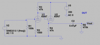
Maybe a couple grid stoppers, but otherwise it's simple and should work great. Lots of room for modifying later on.
It is said that there has to be capacitor between the first and the second stage.
Just hook it up, as is. It will work as shewn.It is said that there has to be capacitor between the first and the second stage.
The difference in harmonic content is a feature of the topology, but is not due to balanced operation. If you believe that the circuit is not single ended I would love to see your analysis on how/why. Got any links or recommendations on reading material for me to check out?
Balanced circuits, such as the mu stage, produce a more distorted, scattered and meager harmonic spectrum. To my knowledge, there is not any reading material providing a physical basis for my assertions, I had to do my own exploration. The analysis necessitates going beyond classical physics. I also made quite detailed notes, unfortunately, the document has become damaged. Is there any chance of restoring a corrupted rtf file? (I doupt it).
It is efficiently accomplished by designing amplifiers as a voltage regulator / oscillator consisting of various balanced stages and techniques imported from the industrial sphere.
Incomprehensible meaningless ad-copy? Who would use negative words in advertising?
1) Instability is an inherent property of balanced topologies Instability conveys high distortion.
2) Circuit solutions inspired by industrial applications are harmful to the audio signal.
OK?
- Home
- Amplifiers
- Tubes / Valves
- 6SN7 Mu follower or cathode follower?