I feel like this thread is just a game of word association
")
It may be helpful if a mod stripped out all the off topic stuff to a containment thread.
Ok, more helpful version if my post before, since I was in a hurry and got sidetracked before I could follow up-
What exact PSU setup are you using? Hum could be from poor filtering, and you're hearing residual ripple, which naturally disappears once the AC is removed. Poor layout could also be a contributing factor. Are you using AC or DC on the filaments? AC can be quiet if done right.
Some more information on your implementation and maybe a few pics of the innards would be very helpful.

I have done with the following changes and when used hum dinger all the noise and hum is gone but the residual of close to 3.5mv peak of 100Hz hum on the output. It looks more like a kind of triangular wave but the pre got much silence after connecting the artificial center tap of the heater to the B+gnd. The entire unit is still on testbench. ( If that could improve with the pre in the chassis ?)
Attachments
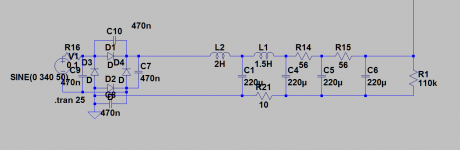
I can do that but that resistor used to isolate that peak charging currents in the ground of the first capacitors as I read it in some article hence the resistance of the choke is 10ohm hence used 10ohm on the bottom to have like balanced filter. But I will remove that and see if there could be any more differences observed.
Your PS as connected is a choke input filter, not capacitor input. So the charging current to the first cap is limited by the 2H choke L2. Normally for small current applications a cap input filter is customary. As well, L2 at 2H may not satisfy the inductance minimum required for the load. What is the load current & voltage?
Is the supply to the bridge rectifier direct off the line or thru a small transformer?
As connected your PS is a hum generator.
Is the supply to the bridge rectifier direct off the line or thru a small transformer?
As connected your PS is a hum generator.
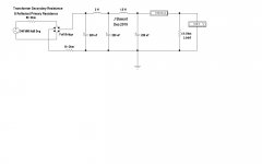
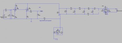
For the simulation I used the numbers on your sim. So for what you are doing not correct but it shows how the parts need to be connected. This one is a capacitor input filter, the capacitor is in the cct before the choke.
For the load you are powering the capacitors in the simulation are on the large size, could normally get the desired result with a lot less.
For the load you are powering the capacitors in the simulation are on the large size, could normally get the desired result with a lot less.
Attachments
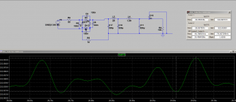
I did the above sim its giving alot of peaks.
I did it as per the link given the book is by Merlin Blencowe
Designing Valve Preamps for Guitar and Bass, Second Edition - Merlin Blencowe - Google Books
you can see in page no 266 to 268
I did it as per the link given the book is by Merlin Blencowe
Designing Valve Preamps for Guitar and Bass, Second Edition - Merlin Blencowe - Google Books
you can see in page no 266 to 268
The link would not open, what kind of peaks are you referring too?
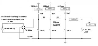
In this sim the AC voltmeters measuring the hum/ripple are set to 10M, same as a common DMM. There are caps in series with each to isolate them from the DC potentials. The hum/ripple is very small after the filter network.
If this is a preamp for a guitar you will probably encounter many problems with stray pickup & ground loops related to the instrument & its connexions.
Can you post a schematic of the amplifier you have built & a photo?
Attachments
Yes the hum is extremely little as much as 3mv and noise is also very little but like said measured on the test bench. We need to see how it performs once in chassis. But having it outside the chassis would acquire interference but slight hum I'm guessing it is coming from the B+.
What if we use Cathode follower? does it have better PSRR?
What if we use Cathode follower? does it have better PSRR?
Attachments
Where is the photo asked for? Need to see the top & bottom of whatever form your construction has taken. That tells a lot about whether it will work. Or not.
We need to see the quality of your construction work before any further advice.
Its just made point to point on bench. PCB for the tube stage is posted earlier.
That is the primary reason you have hum.Its just made point to point on bench. PCB for the tube stage is posted earlier.
This is all going nowhere, time for me to unsubscribe from this thread.
That is the primary reason you have hum.
This is all going nowhere, time for me to unsubscribe from this thread.
will post the pic of the pcb and of the power supply.
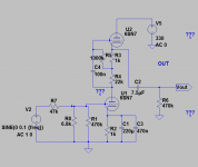
I have tried the following way with CF as well but the same hum residue is there. Which is 100Hz.
I have used the following elevated the heater rails to 60VDC with 220k resistor and 50k resistor and using 100uf cap decoupled to the elevated heater point.
Tried DC heater with 10000uF the hum reduced signficantly but its there.
applied artificial center tap for heater with two x 220ohm resistors and connected that to power ground and also tried with signal ground. Nothing the hum is still there.
Tried chassis wire to B+ gnd and tried both the ways with 10ohm resistor || with 100nF with 35Amp diode bridge.
The hum is still there
Attachments
I just finished building a morgan jones - white cathode follower headphone amp. The amp works, but has a very large hum in both channels. The power supply is a simple design with a bridge rectifier and a 330UF filtering capacitor for the plate voltage and a bridge rectifier and 2200UF filtering capacitor for the filament voltage. Any suggestions on how I can get rid of the hum
- Home
- Amplifiers
- Tubes / Valves
- 6SN7 Mu follower or cathode follower?