I don`t draw lines. What do you mean by "Single Ended Class-A-Holism is addictive!!!" ? Is the mu stage-holism even more addictive?
"I am offering no explanation, please take it or leave it. "

As I see it it the OP has a hum issue and was looking for a circuit that would deal with this problem, but as others have pointed out layout is important no matter what circuit topology is used.Some pics of your amp would help. hum is a bugger to trace sometimes but reading this may help - The Valve Wizard
Also keep any high current AC wires away from sensitive IP's, so use pin 4 of a 6SN7 as IP, not pin 1. Twist heater wiring and route into the corners of chassis. Keep ground wires short, with heavy current parts of the circuit going to ground point first, then lower current or sensistive wiring going in last.
A good place to start when chasing hum issues is to ground your input, any change? Is the hum 50(60)hz or 100(120)hz? Another wrinkle is to get a thin bit of steel sheet, ground it then move it around using it as a shield to block potential EMF. Where is the hum getting in? IP stage or further down the chain?
Andy.
As I see it it the OP has a hum issue and was looking for a circuit that would deal with this problem, but as others have pointed out layout is important no matter what circuit topology is used.Some pics of your amp would help. hum is a bugger to trace sometimes but reading this may help - The Valve Wizard
Also keep any high current AC wires away from sensitive IP's, so use pin 4 of a 6SN7 as IP, not pin 1. Twist heater wiring and route into the corners of chassis. Keep ground wires short, with heavy current parts of the circuit going to ground point first, then lower current or sensistive wiring going in last.
A good place to start when chasing hum issues is to ground your input, any change? Is the hum 50(60)hz or 100(120)hz? Another wrinkle is to get a thin bit of steel sheet, ground it then move it around using it as a shield to block potential EMF. Where is the hum getting in? IP stage or further down the chain?
Andy.
Hi Andy,
Thank you very much for the suggestions. Since I have designed the PCB earlier I didnt knew the importance of using pin 4 as input. Will designa new pcb for it.
Secondly do I really need a regulator for B+ for Mu follower circuit?
I thought of using lm317 as slow ramp start for the heater but once the heater is fixed do i need to look at B+ regulation / ripple eater ckt also?
I have done with the measurements and found out that there is a sinewave from the output is 0.2V peak with 50Hz. Tried using hum dinger but it didnt suppress fully it suppressed only half of it. So the culprit is the heater? Trying with the regulator and will update you regarding that.
Perhaps, but also because the boostrapping imposes a load on the follower. 15k looks quite small for an anode and bootstrap resistor. If boostrapping does not reduce distortion then you are doing it wrong. The 6SN7 is not a particularly good CF valve, because it has low transconductance.
I provided the schematic for review. Can you see a problem?
I followed the basic design procedure from here:
The Valve Wizard
Rp is split in two, equally. A 30k Rp (plate or anode load resistor) is not unusual for a 6SN7.
The feedback from the cathode of the CF is fed back to the midpoint between the two halves of Rp.
Please let us know of your corrections. Thanks.
--
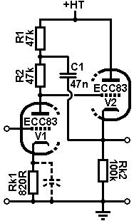
SRPP with added Rk2 load of the cathode follower.
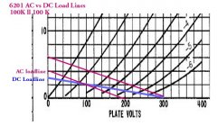
AC vs DC Loadline is a serious problem in this cct, here is why. At first look the load for the CF appears to be 100K. But that is the DC loadline.
The CF load consists of that driving back to the 1st stage plate & resiters as well. Doing the math that load is ~33.9K, all in parallel with the CF Resister of 100K. So the AC loadline is 100K ll 33.9 K, or 25.3 K.
Plotting the AC & DC loadlines on the AX7 CF reveals much even order (2nd, 4th, 6th, ) distortion.
The example of AC vs DC loadlines posted is something I did earlier this year. It is based on the 6201 where the plate load was 100K followed by a grid resister of 100K. If the following grid resistor was 33.9K, the AC loadline would tip much further in a clockwise direction.
A better solution on this topology would use a dissimilar twin triode , ie 6EM7 with the low mu triode as the CF. But if you want a distortion generator, go with this cct.
Attachments
The mu stage exhibits high distortion. I am offering no explanation, please take it or leave it.
"because I said so, that's why"
So you don't like it, and have no cited testing or even anecdotal info to support a statement that can be easily proven wrong?
What the heck man?
I rarely use the circuit but it's very easy to test and compare with actual results to other totem pole or SRPP type circuits. The lowest distortion single tube gainstage that I have ever played with was a mu follower using the 6N16B, even better than the venerable 6SN7. Better than resistor, CCS, or SRPP loading by a far margin.
Last edited:
I have made few observations. One when DC heaters are used the output from the 6SN7GTB from Electro Harmonix has issue with output peaking to close to +/-10V. When Shuguang CV181-z is used there is no sinewave at ouput but when music is played it plays fine.
so im guessing the EH 6sn7 has issues i mean like said I think pin 1 input creating the problem. This time I will change the input pin to pin 4.
so im guessing the EH 6sn7 has issues i mean like said I think pin 1 input creating the problem. This time I will change the input pin to pin 4.
Rp does not have to be split equally; if you are short of voltage headroom then an unequal split may be better. 30k is about the minimum load you can get away with for a 6SN7. Remember that a CF needs a similar load if you want low distortion. As things stand, the CF is driving 30k (cathode resistor) and 15k (boostrap resistor) and 10k (assumed external load), which comes to 5k. A 6SN7 cannot drive 5k successfully.rongon said:Rp is split in two, equally. A 30k Rp (plate or anode load resistor) is not unusual for a 6SN7.
First step is to decide which is more important: being able to drive 10k, or using 6SN7. Then consider raising the supply rail voltage so you can have larger resistor values and so not waste what little drive capability you have in driving the circuit itself.
30K minimum load for low distortion would arrive from four times the plate resistance (Ri). Is there a benefit in using an identical triode for CF and the preceding stage to cancel harmonics? The harmonics spectrum is depending on the loading, changing with aging and varying from sample to sample... so, no sweet spot to arrive at from calculation alone probably.
I didn't build the cct, but I did model it in LTspiceIV. The results are exactly as DF96 predicted. If driving a 100k ohm load impedance (such as might be presented by a vintage-style tube power amp) then the THD is nice and low and the harmonic structure is as expected (mostly 2HD). Drop the load Z to 10k ohms and it falls apart.
If Ia of the 6SN7 is 8mA, then ra will be approx 9k ohms.
Output Z of 6SN7 with 30k Ra is approx 6.9k ohms.
A 30k Ra is more than 4X that, so is an acceptable Ra imo.
If the load Z is 100k, then that 30k in parallel with 100k makes Zload = 23k ohms. That's still marginally acceptable (>3X ra).
The problem is not too low a value of Ra, it is that the 6SN7 CF can't drive a 10k ohm load. So now the question is, will this cct have to drive a 10k ohm load? Or is it destined to drive a 220k ohm load?
Well, I don't know. What is this thing meant to drive? A solid-state power amp?
--
PS - This would work better with a 6N6P or 5687. But the OP is using 6SN7, which is why that's being talked about here.
--
PPS - Of course none of the above addresses the hum issue.
--
Last edited:
IRT the hum issue -- Have you checked your heater wiring/layout?
This article right here on diyAudio caused quite a ruckus a few years back. Good discussion of heater wiring dos and don'ts.
Heater Wiring - the Good the Bad and the Ugly
--
This article right here on diyAudio caused quite a ruckus a few years back. Good discussion of heater wiring dos and don'ts.
Heater Wiring - the Good the Bad and the Ugly
--
For the past decade I've been listening to a 6SN7 mu follower based on Bruce Rosenbilt's 12AU7 mu follower. I built it from parts scavenged from my work. The 6SN7 and 12AU7 have similar specs with the exception that the 6SN7 wants more heater current and prefers much more B+, preferably 300-400V. My transformer could not provide much more than 225V. I later found the 12SX7 sounds better with my lower B+ supply. I originally floated the DC heater supply at about 100V. Eventually I contructed another heater supply tied to ground for the lower tube. Hum was never an issue and the sound has always been fast, smooth and creamy with low distortion. I measured my Zout with the 6SN7 at 1500 ohms. It has no issues with a 12 foot interconnect to my 47Kohm Zin amplifier. My favorite 6SN7s are vintage Sylvanias. 12SX7s are all RCAs.
There's two conversations going off here. To answer the OP's last few posts, it sounds like you do indeed have some coupling of the heater AC getting into your signal path. 200mV is way too much. With a good valve does this improve?
The vunerable parts of the amp is your IP, try scoping the anode (and g1) but keep an eye on your scopes Vmax, for most scopes it's at least 250v and most IP stage anodes are under this, use a separate 630v or higher rated cap if unsure, just tack it on, IE temp solder it on.
Andy.
The vunerable parts of the amp is your IP, try scoping the anode (and g1) but keep an eye on your scopes Vmax, for most scopes it's at least 250v and most IP stage anodes are under this, use a separate 630v or higher rated cap if unsure, just tack it on, IE temp solder it on.
Andy.
No. The two triodes may have the same bias point but they are operating into two quite different loads and have quite different feedback. Better to choose the best triode for each position, unless economy and convenience force you to use the same for each.disco said:Is there a benefit in using an identical triode for CF and the preceding stage to cancel harmonics?
A 6SN7 cathode follower should manage Zout of about 500 ohms when used plain, but this goes up when boostrapping is used. However, it still cannot drive a low load impedance because the output impedance tells you very little about drive capability.RobertHaze said:I measured my Zout with the 6SN7 at 1500 ohms.
200mV hum means a fault is present, either a component fault or a construction fault.
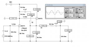
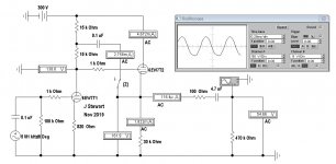
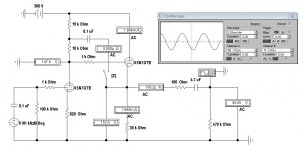
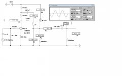
A Comparison, Twin Triode vs Dissimilar Triodes
The 6EW7 was selected as the dissimilar twin triode since section one is similar to section one in the 6SN7GTB. But section two has lower mu but a much higher Gm. In the simulations the 6EM7 is simply replacing the 6SN7GTB, all the passive components are unchanged. So neither cct is optimized.
The +FB can be switched by the key 'Z'.
With optimization the dissimilar triode vers could be expected to perform much better with its higher current capacity. And successfully drive a longer transmission line.
In my work I've found most common coax runs 20-30 pF per foot. For audio the characteristic impedance means nothing. At audio electrical wavelength in transmission lines or space is far too long to be a problem.
Attachments
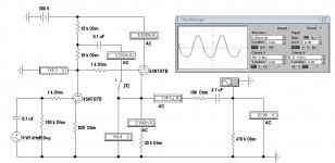
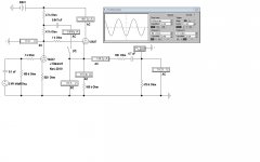
Another Dissimliar Triode Comparison
This series compares the 6FD7 to the 12AX7 cct posted earlier in this thread. The 6FD7 has a high mu triode similar to the 12AX7, so a good starting point. In the same bottle is a low mu triode of high Gm. All of the results are for steady state, sine wave operation. The ccts are not optimized.
There appears to be no significant advantage for use of the 6FD7 alternative. The PFB increases the gain a bit at the cost of greater distortion. Some folks claim to like that. Great for the rock guitarist tho!
Attachments


- Home
- Amplifiers
- Tubes / Valves
- 6SN7 Mu follower or cathode follower?