
The mu follower is associated with high distortion. If distortion matters you should adopt the circuit in post #4.
By who? The mu follower is a very low distortion gain topology when implemented correctly, and it is rather easy to do right. What testing have you found to the contrary?
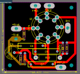
Can anyone tell me anything wrong in the above PCB layout?
Can you post which specific schematic is the basis for that specific PCB layout, with corresponding parts reference numbers shown? (R1, C3, etc.)
--
Can you post which specific schematic is the basis for that specific PCB layout, with corresponding parts reference numbers shown? (R1, C3, etc.)
--
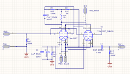
schematic attached
Attachments
I'd sort your power supply out before you do anything. Find a suitable load and scope it. Nailing the hum issue should be first priority.
Andy.
Im using single bridge 5010 followed by CLC 220uF/450V , 2H , 220uF/450V 470k shunt at the output.
Two AC terminals for the heater supply is joined via two resistors each 100ohm and the joint of the two resistors connected to the power ground.
Try DC filament. The problem with many 6SN7 tubes and layout is use of pin 1 as input. The structure of the tube and board layout are critical to eliminate hum.
You also need to elevate the filament so heater to cathode voltage doesn't exceed about 90Vdc.
FYI - the inherent gain gain of the mu follower may just be too high, and the preamp may be picking uo hum.
Again layout is critical
You also need to elevate the filament so heater to cathode voltage doesn't exceed about 90Vdc.
FYI - the inherent gain gain of the mu follower may just be too high, and the preamp may be picking uo hum.
Again layout is critical
I am doing a similar comparison using cascode Ixcp10m45s mu follower vs n
channel source follower. Tubes so far are 6CG7 and 6DJ8. The line preamp is diving a 3 transistor version of 1969 JLH amp.
Prefer the mu version, more clarity and warmth. The source follower has more forward mid range deeper bass. Gain is about the same. Prefer the 6CG7 over the 6DJ8 for the same reasons above.
The only issues are too much gain and tube rush from mu follower. Still tweaking. This my give you another option.
Try DC filament. The problem with many 6SN7 tubes and layout is use of pin 1 as input. The structure of the tube and board layout are critical to eliminate hum.
You also need to elevate the filament so heater to cathode voltage doesn't exceed about 90Vdc.
FYI - the inherent gain gain of the mu follower may just be too high, and the preamp may be picking uo hum.
Again layout is critical
True but is there any suggestion that you can give in the above layout? Its a single layer PCB as I saw no use of going to 2 layer as the wiring is relatively minimal.
schematic attached
You're running two 6SN7 in parallel, then.
The PCB looks like it's meant for running wires from each of the pads for the tube pins to externally mounted tube sockets. (Correct me if I'm wrong about that.) Those flying leads could somehow be picking up hum, especially if the power transformer is located near the audio circuits.
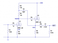
The other option is the bootstrap follower. You feed the output of the cathode follower through a cap back to a split anode load resistor. Advantage low distortion and rejection of the HT supply.
I haven't built one of those, but yes, that's an interesting idea too. However, it would increase gain, which is probably counterproductive for a line stage/control preamp.
Also, the coupling cap from the cathode of the cathode follower to the halfway point of the input tube's split plate resistance will need a quite large value of C for good bass extension. Something like 6.8uF to 10uF would be necessary with a 6SN7.
LTspice seems to think that into typical solid-state amplifier input loads of 10k or so, distortion will be increased over the same circuit without the bootstrapping—I guess because positive feedback increases the output impedance of the cathode follower(?).
See attached schematic. I think it's correct...
Attachments
I've used 6SN7s often & never had hum problems. If there are at the signal level of the amp in this thread the obvious starting point is plug in another 6SN7 first. That shews whether there is an H-K insulation problem. Or not.
If there is a scope available (why not?) check if the hum is at the power frequency (50 or 60 Hz) or if the hum is at double that frequency. That tells us if the problem is in the heater or perhaps a ground loop. If it is double the power freq then most likely PS filtering.
Sofar I see a lot of discussion, thrashing around in the dark & no real test data.
That simply leads down a long tunnel to nowhere & no solution to the fault.
Putting DC on the heater of a defective tube or a poorly laid out cct is a very poor fix. And would not work at all in the real world!!
All the simulations in the world do not replace good test equipment. And the knowledge of how to use it.
Perhaps, but also because the boostrapping imposes a load on the follower. 15k looks quite small for an anode and bootstrap resistor. If boostrapping does not reduce distortion then you are doing it wrong. The 6SN7 is not a particularly good CF valve, because it has low transconductance.rongon said:LTspice seems to think that into typical solid-state amplifier input loads of 10k or so, distortion will be increased over the same circuit without the bootstrapping—I guess because positive feedback increases the output impedance of the cathode follower(?).
The mu stage exhibits high distortion. I am offering no explanation, please take it or leave it.
You are offering no explanation to a nonsense?
Thank you.
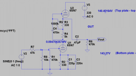
Mu-follower is a common cathode stage loaded on a huge dynamic resistance. Draw a horizontal load line on anode curves and see for yourself what distortions you get compared to load on a resistor.
Which version of the mu stage are you referring to? Schematic please.How was the distortion measured?
The ear does not lie. But the brain interprets the information however it pleases. And conveniently arranges the results to fit the situation.
An example of the application of 'Cookes Variable Constant'. Works every time.
The ear does not lie. But the brain interprets the information however it pleases. And conveniently arranges the results to fit the situation.
An example of the application of 'Cookes Variable Constant'. Works every time.
- Home
- Amplifiers
- Tubes / Valves
- 6SN7 Mu follower or cathode follower?