Noting that small signal pentodes seem to often be more content operating at modest voltages than similar triodes I thought it might be time to become more familiar with them. One thing I noticed is that the RC amplifier charts in many data sheets use rather extreme values of Rl to get astounding levels of gain. I ran some simulations and those values are indeed accurate but lead to very low anode and screen voltages.

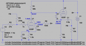
Such high gains are rarely needed in our audio circuits so I ran some simulations with more pedestrian gain values and the results seem pretty nice but I do still have the quiescent anode voltage rather lower than the screen voltage in the following example circuit. is that a concern?

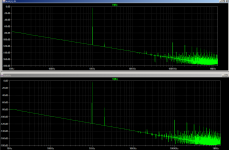
I also noticed that the simulation of the above example circuit shows a several dB bump in the 2MHz range just prior to precipitous rolloff. Is this due to some interaction of the FB with the inter-electrode capacitances? Would it be wise to throw a pole in there somewhere?
Oh, I also note that in the simulation if I use a 300k instead of 100k screen resistor to drop screen voltage down to the vicinity of the anode voltage distortion increases by about 30dB.


Such high gains are rarely needed in our audio circuits so I ran some simulations with more pedestrian gain values and the results seem pretty nice but I do still have the quiescent anode voltage rather lower than the screen voltage in the following example circuit. is that a concern?

I also noticed that the simulation of the above example circuit shows a several dB bump in the 2MHz range just prior to precipitous rolloff. Is this due to some interaction of the FB with the inter-electrode capacitances? Would it be wise to throw a pole in there somewhere?
Oh, I also note that in the simulation if I use a 300k instead of 100k screen resistor to drop screen voltage down to the vicinity of the anode voltage distortion increases by about 30dB.

Last edited:
Yes, it is. The screen is basically acting as the plate, so the simulation is senseless.but I do still have the quiescent anode voltage rather lower than the screen voltage in the following example circuit. is that a concern?
Why do you care about 2MHz?I also noticed that the simulation of the above example circuit shows a several dB bump in the 2MHz range just prior to precipitous rolloff.
GIGO...Oh, I also note that in the simulation if I use a 300k instead of 100k screen resistor to drop screen voltage down to the vicinity of the anode voltage distortion increases by about 30dB.
Thankyou Jazzbo, it didn't seem like a good thing. So the top FFT is basically meaningless due to the faulty biasing. Is there a rule of thumb as to how far above the screen the plate should be at idle? Does it need to exceed screen voltage by the maximum possible output voltage swing or will the screen drop in tandem with the plate when a signal is applied?
My only concern with the MHz range is possible instability and oscillation. Wondering if I should introduce a pole somewhere (where?) in the circuit to insure that doesn't happen. That and I am simply curious as to what the cause of it might be.
My only concern with the MHz range is possible instability and oscillation. Wondering if I should introduce a pole somewhere (where?) in the circuit to insure that doesn't happen. That and I am simply curious as to what the cause of it might be.
Noting that small signal pentodes seem to often be more content operating at modest voltages than similar triodes
Where does it say that?
the RC amplifier charts in many data sheets use rather extreme values of Rl to get astounding levels of gain.
Those high values don't apply to wideband audio, because there is capacitance everywhere. Even with an "infinite impedance follower". You can pencil "1Meg load" but just 30pFd stray and socket capacitance becomes less than 1Meg impedance by 6KHz, 100K by 60KHz, and you express concern about MHz.
I do still have the quiescent anode voltage rather lower than the screen voltage in the following example circuit. is that a concern?
Are these Pentodes or TETRodes?? Do you know the difference? (Beyond grid-count.)
in the simulation if I use a 300k instead of 100k screen resistor to drop screen voltage down to the vicinity of the anode voltage distortion increases by about 30dB.
You probably shifted bias so much you are in a very non-linear zone. Lower G2 voltage means less power output (must use higher-Z load) but increases voltage gain. Look at your DC voltages and signal swings.
Where does it say that?
Just my impression from browsing the data sheets looking at operating points listed and the curves. most small signal triodes don't get out of the knee until you get to a fairly high plate voltage v.s. the typical pentode curves. The 12AU7 seems to be an exception.
Are these Pentodes or TETRodes?? Do you know the difference? (Beyond grid-count.)
Pentodes I believe (example circuit is a 6U8 and the chart is from the 6AU6 data sheet). I do know the basic difference but the point of this thread is for me to learn more about pentode operation so any detailed implications that you can explain would be welcome. I do tend to miss the obvious sometimes (in school when the textbooks state "and it is intuitively obvious that..." my response was often "oh is it now?
Manipulating the screen for compression effects and the like is something git amp guys have been doing for a long time.
This shows effect:
The Valve Wizard
Cheers,
Ian
This shows effect:
The Valve Wizard
Cheers,
Ian
There are multiple interacting variables at play in a pentode gain stage. What's right for a particular circuit depends greatly on what it's being used for and the requirements of the gain stage.
I was playing with an input stage for a guitar amp and I wanted a HUGE adjustable bucket full of gain (up to a V/V of 1000), some dynamic compression that transitioned into good sounding distortion, and a frequency response that didn't roll off the guitar's highs (5 to 8 KHz). I only had a B+ of 160 volts, and it was coming from the screen grid supply to the output tubes which would drop off rapidly as the output tubes entered clipping (125 volts at full crank).
Requirements like this can't be simulated, so I put together a breadboard with a 6AU6 and 3 pots. I used a mosfet bootstrap circuit for a plate load which could get me an effective AC load impedance on the tube that was adjustable from 100K to somewhere in the 1.5 megohm range (one pot). I also had a pot on the screen grid, and in the cathode circuit.
I spent about a week with several guitars playing with this and it was a very informative week. The plate load pot is permanently installed in the resulting amp, but I settled on fixed resistors for the screen and cathode circuits. I did decide that my "ultimate" guitar amp will have a few selectable choices for these parts.
It may be a worthwhile exercise to step away from the simulator and play with a real tube, a sig gen, a scope, and a hand full of pots for a while. Write down your observations, then take them back to the computer.
I find that LT Spice does OK when using a vacuum tube inside its expected use case and staying within a primarily linear mode of operation. Some vacuum tube models seem to work better than others.
Microphony is the limiting factor in the high gain input stage in my guitar amp. It also gets worse with time if you leave the amp head on top of the speaker cabinet. I am using 18FW6 tubes which are 18volt 6AU6's. I had to try a handful to get one that won't bust into acoustic feedback when the head is on the speaker cabinet and all the knobs are dimed. There is so much gain at that point that the guitar CABLE becomes microphonic.
I use the pentode for gain, followed by the tone stack then a triode to make up for the tone stack loss. It has been suggested to swap the two stages, and I may try this next time I rip into the amp, or dig the prototype back out of the "bone pile." I'm pretty happy with the amp as is so it hasn't been touched in about 2 years.
I use the pentode for gain, followed by the tone stack then a triode to make up for the tone stack loss. It has been suggested to swap the two stages, and I may try this next time I rip into the amp, or dig the prototype back out of the "bone pile." I'm pretty happy with the amp as is so it hasn't been touched in about 2 years.
- Status
- This old topic is closed. If you want to reopen this topic, contact a moderator using the "Report Post" button.
- Home
- Amplifiers
- Tubes / Valves
- Getting to know small signal pentodes