I have a Dynaco St 70. I have attached the 7199 front end with all voltages from my amp written on the schematic. I have also noted the voltage drops across most of the resistors surrounding the tube. These measurements were with 7199 tubes. (6gh8a are similar). Here is my question. How can the pentode anode be injecting 100 VDC into the grid of the triode section without burning up the triode section? I have calculated .63ma on the pentode plate with about .195ma on the screen. My triode calculation shows 2.54ma. Do these current seem close based on this information? Last question, the 7199 data sheet indicates the curves were drawn with a much higher screen and plate voltage. How does one use these data sheets to draw the load line/voltages I have measured here? for example the screen voltage o the tunes is only 27 vdc?
Thanks for any help.
Thanks for any help.
Attachments
According to your measurements the grid of the triode section is -9V with respect to its cathode. The grid doesn't burn up because it's not pulling any current from the cathode. I suggest you do some reading here: The Valve Wizard
Last edited:
been trying to learn the "mechanics" of how this one amplifier works.
This is a direct-coupled circuit. It is designed so the phase splitter tube (second stage) needs the same DC voltage at its grid, as the voltage amplifier (first tube) has at its plate. So, they can be directly connected and the circuit will function as it should.
Tubes work based on the relative voltages on the grid, cathode, and plate. Voltages only have meaning between two points. That's why your meter has two leads.
The second stage cathode resistor is larger than a typical cathode resistor, since this is a phase splitter, which has equal, large value (47k) plate and cathode resistors.
Last edited:
Rayma, does this mean that the AC signal voltages are amplified to plus and minus 50V to the EL34 grids? This adds up to 100 V. I also assume that that signal voltage is riding on the direct coupled 100V. And yes I am still experimenting thanks to DIYAUDIO forums advice and explanations. Thanks.
> plus and minus 50V to the EL34 grids? This adds up to 100 V. I also assume that that signal voltage is riding on the direct coupled 100V.
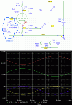
Looks about like this. Triode K and P swing around their DC values. 0.1u coupling caps shift the DC to the -33V bias voltage but pass the audio swings. My sim says 50V is too much so I ran with 40V peak swing, very similar.
Looks about like this. Triode K and P swing around their DC values. 0.1u coupling caps shift the DC to the -33V bias voltage but pass the audio swings. My sim says 50V is too much so I ran with 40V peak swing, very similar.
Attachments
does this mean that the AC signal voltages are amplified to plus and minus 50V to the EL34 grids?
This will vary with the input pentode's gain, but somewhere around +/- 30V peak. Typical output tube DC grid bias voltages run anywhere from -32V to -45V, depending on the output tubes' age and brand. BTW, make sure your coupling capacitors are not leaking. There should be virtually no DC voltage drop across the four 270k output tube grid resistors. If there is, you have leakage in that coupling capacitor. If you still have the Black Cat paper capacitors, just throw all 6 of them out without bothering to test. They'll leak sooner or later.
If you find that you get asymmetrical peak voltages out of the phase inverter, you can reduce the value of the input pentode's screen grid resistor from 1.5M to around 1.3M-1M, just until the swing is symmetrical.
Last edited:
PRR & Rayma,
Thanks so much for your knowledge. I do not have the ability to check for waveform symmetry. I did check the dc voltage drop on the 270k resistors. This is a brand new board from dynakits so it has all new capacitors and such on the board. it is less than two years old. I measure 5MV across the resistors with my DVM. I know this could be my DVM function as it is nothing fancy. PRR thanks for your schematic. I will study this to make sure I try and understand the technical aspects of the tube functions.
Thanks so much for your knowledge. I do not have the ability to check for waveform symmetry. I did check the dc voltage drop on the 270k resistors. This is a brand new board from dynakits so it has all new capacitors and such on the board. it is less than two years old. I measure 5MV across the resistors with my DVM. I know this could be my DVM function as it is nothing fancy. PRR thanks for your schematic. I will study this to make sure I try and understand the technical aspects of the tube functions.
- Status
- This old topic is closed. If you want to reopen this topic, contact a moderator using the "Report Post" button.
- Home
- Amplifiers
- Tubes / Valves
- Dynaco ST70 Pentode/Triode Voltages