I've got a pair of 7C5 (loctal 6V6GT) and thought I would try designing an integrated SE amp that can directly play sources such as a CD player, computer, or phone. If any of the circuits end up sounding exceptional, I might do a final build of a speaker and headphone amp with a pair of Raphaelite 5.5K to 8R & 32R OPTs. At some point I might be interested in trying gas voltage regulator tubes, in traditional shunt configuration or in series like Decware does with the Mini Torii.
Input tube candidates in my stash are 6SJ7, 6SC7, 6SQ7, and 6AC7.
Right now I'm using a pair of 5K:8R, 100mA, 15W Electra-Print OPTs.
First, I built the Bates direct connected cathode follower amp just for the heck of it. It had a very nice, natural sound but at 1/2 a watt or so was too quiet for my 87db el cheapo test speakers. It's definitely a candidate for a headphone amp, though.
Then, since I've never worked with a pentode or beam tetrode before, I decided to start working with 7C5 in triode mode, using the GE 6V6-GT datasheet for reference.
Since I've used 6SJ7 to good effect in the Sound Practices WE91A as well as the Bates DC amp, I thought I'd try using it to drive a traditionally wired 7C5 that takes the output signal off the plate. For the input stage, I began with the RCA Resistor Coupled Chart for commonly used audio input tubes, picking a row in the 300V B+ section:
Rp 100K
Rg 100K
Rg2 350K (I could only find 340K at my electronics store, and am using that)
Voltage Gain 67
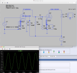
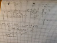
I breadboarded the circuit (schematic attached) and am listening to luxuriamusic.com as I type this. The attached LTSpice schemo accurately reflects the voltages I measured at those nodes. You'll see that my B+ is 266V, with 258V on the 7C5 plate and 12V on the cathode, for 246Vak. Slightly under the recommended triode operating points in the 6V6GT datasheet, but close enough for now, and it sounds good.
The power supply is:
PT 540VCT
1 x 5Y3GT
Single power supply rail: 22uF -- 6H (148R) -- 22uF -- 2.5H (39R) -- 22uF
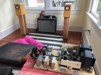
Hum is quiet but audible when music is not playing, so higher capacitor values and/or larger value chokes would help. Also it's unenclosed and everything's a rat's nest.
I figure output power is roughly 1.5 watts. It can drive the sound on my 89db single full range driver speakers (Fostex FE103Sol) to earsplitting levels before it overdrives and distorts. I certainly don't need the 4.5 watts from pentode mode for this setup, but will try it later anyway just to hear what it sounds like.
For a next step, I might choose one of the lower gain operating points for the 6SJ7 (e.g. the row in the 90V Ebb range resulting in a Voltage Gain of 41) or putting it in triode mode for the amplification factor of 19.
Input tube candidates in my stash are 6SJ7, 6SC7, 6SQ7, and 6AC7.
Right now I'm using a pair of 5K:8R, 100mA, 15W Electra-Print OPTs.
First, I built the Bates direct connected cathode follower amp just for the heck of it. It had a very nice, natural sound but at 1/2 a watt or so was too quiet for my 87db el cheapo test speakers. It's definitely a candidate for a headphone amp, though.
Then, since I've never worked with a pentode or beam tetrode before, I decided to start working with 7C5 in triode mode, using the GE 6V6-GT datasheet for reference.
Since I've used 6SJ7 to good effect in the Sound Practices WE91A as well as the Bates DC amp, I thought I'd try using it to drive a traditionally wired 7C5 that takes the output signal off the plate. For the input stage, I began with the RCA Resistor Coupled Chart for commonly used audio input tubes, picking a row in the 300V B+ section:
Rp 100K
Rg 100K
Rg2 350K (I could only find 340K at my electronics store, and am using that)
Voltage Gain 67
I breadboarded the circuit (schematic attached) and am listening to luxuriamusic.com as I type this. The attached LTSpice schemo accurately reflects the voltages I measured at those nodes. You'll see that my B+ is 266V, with 258V on the 7C5 plate and 12V on the cathode, for 246Vak. Slightly under the recommended triode operating points in the 6V6GT datasheet, but close enough for now, and it sounds good.
The power supply is:
PT 540VCT
1 x 5Y3GT
Single power supply rail: 22uF -- 6H (148R) -- 22uF -- 2.5H (39R) -- 22uF
Hum is quiet but audible when music is not playing, so higher capacitor values and/or larger value chokes would help. Also it's unenclosed and everything's a rat's nest.
I figure output power is roughly 1.5 watts. It can drive the sound on my 89db single full range driver speakers (Fostex FE103Sol) to earsplitting levels before it overdrives and distorts. I certainly don't need the 4.5 watts from pentode mode for this setup, but will try it later anyway just to hear what it sounds like.
For a next step, I might choose one of the lower gain operating points for the 6SJ7 (e.g. the row in the 90V Ebb range resulting in a Voltage Gain of 41) or putting it in triode mode for the amplification factor of 19.
Attachments
Last edited:
Cool! If you do a build thread I'll be sure to follow.
I listened to the amp a little more today. The sound is opening up because the coupling caps -- a pair of NOS paper-in-oil, 0.15uF 400V, by PC -- and the screen grid caps -- NOS Cornell-Dubillier Black Cat 0.1uF 1000V -- are burning in.
Also switching from luxuriamusic.com to the Alfred Apaka channel on Pandora resulted in a *much* better signal quality.")
I listened to the amp a little more today. The sound is opening up because the coupling caps -- a pair of NOS paper-in-oil, 0.15uF 400V, by PC -- and the screen grid caps -- NOS Cornell-Dubillier Black Cat 0.1uF 1000V -- are burning in.
Also switching from luxuriamusic.com to the Alfred Apaka channel on Pandora resulted in a *much* better signal quality.
Question about attenuation for headphone use. My headphones are 32 ohm Beyerdynamic DT-880, rated for a "power handling capacity" of 100mW.
I've got a pair of OPTs with dual secondaries that can be wired for 8 ohm (to speaker) or 32 ohm (to headphone), and I've figured out a way to use a 3PDT switch to toggle between the two.
With the 7C5 running in triode mode, at about 1.5 watts, would I fry the headphones if I don't attenuate the output from the 32 ohm secondary?
If I need to attenuate, what would be the best way to do that? Since the impedance is already matched, perhaps a simple resistor in series between OPT secondary and headphone jack would be sufficient? Or would I want to use something like an L-pad or T-pad (or something else)?
> would I fry the headphones if I don't attenuate
If you are wearing the headphones, you will probably fry your ears before the headphones. Will you sit there stunned-deaf? Or turn-down?
Is a real question. I have often had headphones for setup with speaker systems, and forgot to unplug, didn't notice the small screams from the cans over the large sound from the speaker, and sometimes killed my cans.
_IF_ you will act as an adult: don't fry your ears, the cans will probably be fine. Due to the peak/average ratio of speech/music, you "want" peaks which the phones won't sustain long-term. 10X is reasonable. 1.5W is 15X which is still fine.
The '880 are claimed 96dB SPL, probably re:1mW, which means 100mW is 116dB. This is VERY LOUD, like sticking your ear into a 40 Watt guitar amplifier. 1 whole Watt is 126dB SPL and even for a split second, you will NOT enjoy that clamped to your head.
Thanks for the warning. I'm not into hurting my ears. I'd raise the volume very carefully from 0, but the stereo tracking on my volume pot is not great in that region and would likely be too loud by the time it summed correctly.
Re: the danger of frying cans accidentally left plugged in while speakers are playing -- I figured out how to use a 3PDT switch with my OPTs to toggle between headphones or speaker. It would be impossible for both to be live at once, and I wouldn't switch them while the amp is running.
OK, so I'll put an attenuator network between OPT secondary and the headphone jack. The question remains, though, as to what is the best method for this application, where we already have a 32 ohm secondary matched to a 32 ohm headphone -- L-pad, T-pad, simple series resistor, something else?
I tried two more operating points for the 6SJ7 today, using the RCA resistor chart for audio input tubes.
I'll refer to the version in post 1 as #1.
#2
Ebb -- 90V
Rp -- 100K
Rg -- 100K
Rg2 -- 290K
Rk -- 820R
Cg2 -- 0.1uF (the sheet calls for .09uF -- close enough)
Ck -- 47uF
C -- 0.15uF
Eo -- 18V
Voltage Gain -- 41
#3
Ebb -- 180V
Rp -- 100K
Rg -- 100K
Rg2 -- 290K
Rk -- 750R (didn't have enough room on the breadboard to add a 10R resistor in series -- close enough)
Cg2 -- 0.1uF
Ck -- 47uF
C -- 0.15uF
Eo -- 49
Voltage Gain -- 55
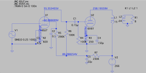
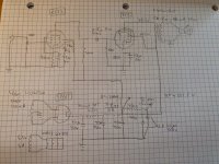
Attached screenshots of LTSpice show the voltages measured in the actual circuit (good models, designers. Thank you!).
#2 is noticeably less dynamic and lacked body (sounded a bit thin and hollow) compared to #1 and #3.
Right now I'm undecided whether #1 or #3 is better. #1 had wonderful harmonic development and was very dynamic and detailed. #3 is very similar, but possibly a little more controlled and might have an edge where detail is concerned. It also sounds a slightly better balanced overall than #1. But #1 is more exciting to listen to.
The gain in the input stage is certainly higher than it needs to be. I've been controlling the volume with the iPhone. Even clicking one step louder or softer results in a big change in volume. With the lowest gain setting (#2), the iPhone was at about half volume (it has 1V output at full volume), and it very loud.
If I have enough time to fiddle with this tomorrow, I'll try the 6SJ7 in triode mode (amplification factor of 19).
I'll refer to the version in post 1 as #1.
#2
Ebb -- 90V
Rp -- 100K
Rg -- 100K
Rg2 -- 290K
Rk -- 820R
Cg2 -- 0.1uF (the sheet calls for .09uF -- close enough)
Ck -- 47uF
C -- 0.15uF
Eo -- 18V
Voltage Gain -- 41
#3
Ebb -- 180V
Rp -- 100K
Rg -- 100K
Rg2 -- 290K
Rk -- 750R (didn't have enough room on the breadboard to add a 10R resistor in series -- close enough)
Cg2 -- 0.1uF
Ck -- 47uF
C -- 0.15uF
Eo -- 49
Voltage Gain -- 55
Attached screenshots of LTSpice show the voltages measured in the actual circuit (good models, designers. Thank you!).
#2 is noticeably less dynamic and lacked body (sounded a bit thin and hollow) compared to #1 and #3.
Right now I'm undecided whether #1 or #3 is better. #1 had wonderful harmonic development and was very dynamic and detailed. #3 is very similar, but possibly a little more controlled and might have an edge where detail is concerned. It also sounds a slightly better balanced overall than #1. But #1 is more exciting to listen to.
The gain in the input stage is certainly higher than it needs to be. I've been controlling the volume with the iPhone. Even clicking one step louder or softer results in a big change in volume. With the lowest gain setting (#2), the iPhone was at about half volume (it has 1V output at full volume), and it very loud.
If I have enough time to fiddle with this tomorrow, I'll try the 6SJ7 in triode mode (amplification factor of 19).
Attachments
I've done lots of listening to this circuit over the past several weeks with the 7C5 in triode mode, 6SJ7 with 340K Rg2, and think it worthy of a final build.
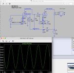
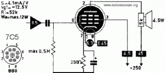
Today I wired the 7C5 in tetrode mode based on the resistor chart for that tube (attached). To get the 250V supply voltage, I added a 350R resistor and 22uF capacitor per channel to the power supply filter (it resulted in 251.5V). To my surprise, the amp was quieter. I had to turn up the volume nearly all the way to be able to hear it, and by that time it was overdriven and sounded like electric guitar distortion (acoustic slide guitar in Hawaiian music sounded like it was purposely [and even nicely] distorted -- kind of funny).
The 7C5 resistor chart and schematics for triode and pentode mode are attached here.
Not many of the existing single-ended 6V6 tetrode schematics run the tube in that way, yet I was surprised that going by the book resulted in poor sound quality. I should draw out load lines to start getting a sense of how to run the 7C5 in tetrode, but might not be able to get back to this for a few days, so thought I'd post the results here. At any rate, you can see the attached schematics for a sense of what I've been working with.
Attachments
Beam power tetrode and true 3 grid power pentode are "equivalent"; see 6CA7 and EL34. Max. open loop linearity of full pentode mode "finals" is obtained by regulating g2 B+ at a fraction of anode B+. In particular, the amount of highly irritating intermodulation distortion is lowered. FWIW, I suggest changing the rectifier to a 5AR4, in order to raise the B+ rail voltage, and using either a 0A2 or 0D3 to regulate g2 B+. Mere voltage does not (within reason) cause damage. Excessive dissipation is the tube killer. Keep plate dissipation just below 12 W. and all will be well.
Damping factor may not matter with headphones. However, damping factor, most definitely, does matter with speakers. Full pentode mode must have the help of loop NFB, in some form, or the damping factor will be unacceptable. Your O/P "iron" is massive enough to allow either a "text book" GNFB loop or the so called plate to plate short loop. AAMOF, you could combine the 2 techniques.
Damping factor may not matter with headphones. However, damping factor, most definitely, does matter with speakers. Full pentode mode must have the help of loop NFB, in some form, or the damping factor will be unacceptable. Your O/P "iron" is massive enough to allow either a "text book" GNFB loop or the so called plate to plate short loop. AAMOF, you could combine the 2 techniques.
Last edited:
Max. open loop linearity of full pentode mode "finals" is obtained by regulating g2 B+ at a fraction of anode B+. In particular, the amount of highly irritating intermodulation distortion is lowered. FWIW, I suggest changing the rectifier to a 5AR4, in order to raise the B+ rail voltage, and using either a 0A2 or 0D3 to regulate g2 B+.
Do you have recommendations on how to implement tube regulation? I've looked into this, and most instances indicate using the gas regulator as shunt to ground, lit by a threshold condition of something like 140V/5mA, and bypassed by a capacitor of less than, say, 0.1uF, to reduce noise and prevent oscillation. I've also seen that outfits like Decware implement the gas regulator tubes in series with the supply grid, but I've not been able to find information on how that is done.
Full pentode mode must have the help of loop NFB, in some form, or the damping factor will be unacceptable. Your O/P "iron" is massive enough to allow either a "text book" GNFB loop or the so called plate to plate short loop. AAMOF, you could combine the 2 techniques.
It'll take while to get some gas regulators here, so I'll look into feedback. Thanks!
Dunno what Steve Deckert did/does. Shunt regulator, with a carefully selected current limiting resistor is "classic". I favor a 0.047 to 0.068 μF. cap. in parallel with the gas regulator tube, for noise control. A 0.1 μF. part exposes the setup to an outside chance of unwanted relaxation oscillation and more capacitance increases the odds of trouble occurring.
Read this GE PDF. It's a pretty good place to start in learning about gas discharge regulator tubes. Both the Octal base/ST bottle 0D3 and the 7 pin mini 0A2 are "150" V. parts. A single regulator will be adequate for the screen grids of the 2X SE "finals".
Read this GE PDF. It's a pretty good place to start in learning about gas discharge regulator tubes. Both the Octal base/ST bottle 0D3 and the 7 pin mini 0A2 are "150" V. parts. A single regulator will be adequate for the screen grids of the 2X SE "finals".
Read this GE PDF. It's a pretty good place to start in learning about gas discharge regulator tubes. Both the Octal base/ST bottle 0D3 and the 7 pin mini 0A2 are "150" V. parts. A single regulator will be adequate for the screen grids of the 2X SE "finals".
Excellent! Thank you. Surprised I never came across that PDF in my searches.
Jeff
jdrouin,
I like your 7C5 amp idea.
If the Raphaelite transformers have an Ultra Linear Tap, you can try putting the screens on that tap. But UL mode has more gain than triode mode, so you probably would need to triode wire the input pentode.
I do not remember hearing noise in my amplifier that used an OD3 gas tube regulator.
The gas regulator was unbypassed.
A typical gas regulator has about 100 Ohms of dynamic resistance.
And how much noise reduction could you get if you bypass 100 Ohms dynamic resistance, even with a capacitor as large as 0.1uF?
0.1uF is 159 Ohms at 20kHz.
0.1uf is 1,590 Ohms at 2kHz.
That is not a low enough impedance to reduce any audio frequency noise of a gas regulator tube.
More capacitance, and now you have a relaxation oscillator with many 10s of volts on the screen (now that is noisy).
A very small bypass cap across a gas regulator tube might make a difference in noise on a receiver that had an AM tuner.
Last edited:
Thanks for the added info on gas regulators.
The Raphaelite transformers have two 16 ohm secondaries. Since they are wired in series for 32 ohm, I suppose it’s possible to make a center tap at the junction. They are wired in parallel for 8 ohms, which would not provide a center tap.
Funny you should mention the Raphaelites because Just an hour ago I swapped them in to the breadboard in 8 ohm mode. The 7C5s are still in triode. The Raphaelites primary DCR is much higher than the E-Ps, putting the plate at 250V for a voltage across the tube of about 239v.
I’m going to add another 5Y3GT to make a pseudo dual mono power supply. That should raise the voltage a little and also allow me to assess if it’s any better than the single rail supply. The single 5Y3GT handling the whole circuit is running really close to max capacity, and it would be good to take some of the load off. .
jdrouin,
The Ultra Linear tap I was talking about has to be on the Primary winding, not on the secondary winding. Many transformers do not have an UL tap.
Using the Raphaelite secondaries wired in parallel (8 Ohm mode, careful to wire them in phase), will work both for 32 Ohm headphones (I think you have plenty of excess gain), and work for 8 Ohm loudspeakers.
Gah! Right. I was in caffeine deficit when responding before. ;-)
I figured out a way to use a 3PDT switch to toggle between 8 ohm to speaker and 32 ohm to headphones (I have a pair of 32 ohm Grado's and a pair of 32 ohm Beyerdynamic) without having to unplug anything.
Wouldn't using the 32 ohm headphones on the 8 ohm secondaries wreak havoc on the load impedance of the output tube? With the 5.5K primaries of the Raphaelites, it would reflect back a 22K load impedance.
As long as the phones are sensitive enough, the 7C5 plate's voltage excursion would not exceed the tube and transformer voltage ratings, and there would not be clipping.
And . . . there would be less distortion.
And . . . there would be 6 dB less hum and noise in the earphones.
And . . . there would be less distortion.
And . . . there would be 6 dB less hum and noise in the earphones.
I would hope you are using a volume control at the input to the amp.
In that case, you could directly connect the 32 Ohm phones to the 8 Ohm tap.
(and remember to start with the volume turned down).
You get less distortion that way.
Otherwise, if there is too much hum that way, and you can not reduce hum further, a couple of resistors could be used for each channel at the earphone output (fixed termination and attenuation, which would be my next choice).
But that would require a resistor across the 8 Ohm output, and a series resistor from there to the earphones.
The problem would be if you want to use loudspeakers, you need to disconnect the termination resistor that is across the 8 Ohm output that is used in earphone mode.
You would need a switch that allows operation modes for loudspeaker use; and for the earphone use with resistor load and attenuation resistor for the earphone. And it has to switch both channels.
Last edited:
- Status
- This old topic is closed. If you want to reopen this topic, contact a moderator using the "Report Post" button.
- Home
- Amplifiers
- Tubes / Valves
- Designing an SE 7C5 Amp