SEP using 6P30B and 5744WB/6S7B-V
Hi,
To start off I should state that this is my first attempt to design and build anything using vacuum tubes, and I have much to glean from the books I've bought.
I searched here and on the interweb in general and there isn't a huge amount of info regarding the 6P30B tube, a couple of threads here, a few of Wavebourn designs/you tube videos.
So, I've skipped forwards a couple of steps....
Being a first attempt at tube circuit design, I built a simple voltage amplifier, fully bypassed Rk, drew the loadlines for 150k Rload and Va of 2/3rds B+.
In testing using 6C7B or 5744WB (mu~ 70), all is well and I see OLG approaching 2/3rds Mu.
Great!
Last edited:
A power stage
Then, after reading around an awful lot, and going over the information again and again I found that TheGimp made a very helpful point in post #4 here:
Anyone have experience with transformers for a 6p30b-r PP Amp?
So I started to try an build a pentode power stage, using the data points mentioned, and I varied Vg2, Va, and Ik to arrive at something that just about stays within datasheet limits (I.e. for max watts)
I figured I should be able to make 25% efficiency, so perhaps1 Watt output, perhaps a shade more.
Imagine my horror when I barely made 0.5W using a 100v line matching transformer on 1W tap (IIRC about 3k)!!!
Then imagine my embarrassment when I realised I wired the 6P30B-R tube using the pin out of the 6P30B....
I still haven't bothered to ascertain what I was driving the tube with, which grid or other electrode, but somehow it still worked in an inefficient manner.
So...courtesy of auction sites, I had a old radio output transformer 7k:4R....studying all the information I had seen, this is still too high reflected Z, but its what i had to hand so I went back to the amp and hooked it up.
Much better! 0.8W.....limit of the sig gen output...
Triode stage to drive pentode
Taking the simple triode stage from before I initially ran with feedback to the grid to get around 30 V/V gain, found that I ended up running into soft clipping before the cut off clip occurred. Reducing the gain helped slightly, but of course required higher drive.
I then built an lower gain stage using 6C6B with a lower mu and better current capability.
This helped but not nearly as much as tweaking the Vg2 voltage, and adding plate feedback to control the gain.
This is where things get hazy. I merely added a large value feedback resistor following a blocking capacitor, and reduced it until I got a result which seemed good on the scope. I started around 1M and ended about 132k.
So I now have:
Va = 300V
Vg1 = 38 - 40V
Rleak= 150k
Va-k = ~260V
Vg2 = 250V (datasheet maximum for 6P30B)
Rg2 = 68k
Rk1 = 2k
Pdiss ~5.55 W
Po = 1.2 W (before clip on scope)
I've yet to redraw the loadlines and see where I'm at for either drive stage or output stage, so that is a work in progress.
Doubtless I'm exceeding the triode datasheet specs (in voltage) and I need to revisit that, and reduce them accordingly.
I will also cool the bias slightly to stay more in the range 4.5 to 5 W dissipation, and I'll post the revised schematic once I'm done.
Any advice or suggestions of improvement are welcome (once I post an up to date schematic so that there's something to criticise!)
Last edited:
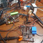
Some pictures for those that like to see creative point to point antennae...
Oh I forgot...In my travels I tried small 3mm low current red LED for bias, and actually reply liked the effect this had, and the 1.7V bias was quite a nice point, (the cathode bias ~0.7V) driving ability was improved.
I really need to read up more on LED bias....
Oh I forgot...In my travels I tried small 3mm low current red LED for bias, and actually reply liked the effect this had, and the 1.7V bias was quite a nice point, (the cathode bias ~0.7V) driving ability was improved.
I really need to read up more on LED bias....
Attachments
As promised...schematic attached
Hi,
First off, here is a schematic of the circuit I have this far (attached) including measured electrode voltages (using 7k:4R OPT) Drawing a schematic at stages in a build is always a good idea - I find most of my errors when re-visiting the schematic/re-drawing the schematic!
Secondly, I have noticed some errors and was already aware that some of my component values, selected by experimentation, may need re-calculating (or just calculating).
So....
1) I must look at the RC filter on the grid of both tubes, as so far I have only added a series resistance Rg, and no additional capacitor from grid to gnd.
2) The R element of the input RC isn't in the right place - it should be 'inside' the grid leak R, nearest the tube.
3) the Values of Rg and Rf for both tubes needs to be re-calculated (Rg in both tubes ended up being much smaller than ra, so either I need to compensate with capacitance, or alter the values of Rf and Rg to yield the same gain.
4) There is probably more wrong with my circuit....like the use of screen degeneration....
However, testing today with a transformer suitable for ECL86 (4k:8R), bias shifted slightly, Vg2 slightly up at 260V. Ill need to review the design and lower this back to <250V. MORE POWER! I'm now getting a max output before clipping of 1.5W into 8R
Attachments
Last edited:
Several things…
From the 5744 tube datasheet (TungSol), and your design-point of having a B+ → VA[/aub] drop of about 100 volts (giving a VA of 200 V more or less), with a 33 kΩ load resistor and E=IR,
E = I R
100 = I 33,000
I = 0.00303 A
So, this logically will be going thru the cathode, too of the 5744. Thing is, what VK (to use the German K for Kathode, as C looks suspiciously like a Capacitor when one's eyes are squinting at 3 AM) is needed?
Go to the TungSol sheet. Find the curves, and locate the curve that best fits VA = 200 V and IA = 3.03 ma. Ah… there it is … about 2.0 volts on VK.
Well, that right there tells me that the 330 Ω RK resistor, dropping only 1 volt, is not the right size. You could employ Ohm's law easily enough, and see that a 620 Ω (nearest 5% value) would fit the bill. OR (if you keep reading these lovely weblogs), you'll also hit on the idea that an ordinary RED LED would do the job just as well. After all, the combo of a resistor + bypass capacitor is a teensy weensy power supply.
I'd go with the LED, myself.
Just make sure it is a common one. No ultra-super-bright thing.
PS: it isn't at all clear why you're feeding back some of U1's anode output back to its grid: hopes for negative feedback linearization? I wouldn't myself. But that's me.
PPS: I see that your measured VA is closer to 150 volts.
This makes more sense…
As it increases current to about 4.5 ma, which increases the VK to about 1.5 volts, which then brings it all into balance. See? Curves… wonderful curves…
No comment re: final stage. It looks nominally correct.
Your output transformer tho' doesn't likely have a 1 Ω primary. (the "1" in the drawing)
Just saying,
GoatGuy
GoatGuy,
Thanks for the reply.
I should comment that the 5744 gain stage was originally designed via loadlines for a somewhat lower B+ (210V) and I neglected to rebias properly after increasing the B+ to 300V.
With Original B+ of 210V and Va of 2/3rds, the Q point intersects around the 0.7V mark, requiring 220R cathode resistor.
And you're quite right, the use of a low current red LED give bias around 1.7V and I liked it a lot!
I think I biased with 560R to get closer, then went back to LED.
I need to study more (or just insert a small resistor) to understand better how I can measure the DC current when using LED bias)
Several things…
PS: it isn't at all clear why you're feeding back some of U1's anode output back to its grid: hopes for negative feedback linearization? I wouldn't myself. But that's me.
I'm a little confused by this comment...
Are you saying I shouldn't be using any local feedback around the triode?
Can you explain further?
Initially I ran the triode open loop (and so the pentode...), after degenerating the pentode because gain was rather high, then I went back to the triode and degenerated that too.
I've noticed that I made an error on the schematic, plate voltage, Va, is labelled twice.
To clarify, using red LED or 560/680R for cathode bias, yields plate voltage of 150V at Vgk of 1.7V
Plate voltage in current set up (330R cathode resistor) is 195V, with Vgk of 1V. Close to 2/3rds B+, but not the correct bias for centre biasing for max voltage swing.
Sorry for the confusion.
IIRC at either bias point, the triode still has headroom, Well after the pentode grid is driven far enough to clip the output.
I had systematically reduced gain in the pentode, to use more of that voltage overhead from the triode, but after several iterations, i think i found the best gain in the output stage.
I.e. reducing output stage gain to use a larger proportion of the triode voltage gain, didn't really work. Triode loading increased, and the headroom I had, disappeared. So I reverted to the best set up.
Last edited:
GoatGuy, Thanks for the reply. I need to study more (or just insert a small resistor) to understand better how I can measure the DC current when using LED bias)
Easy enough: in DC conditions (i.e. no signal or as we say "quiescent"), just measure the volt drop across RA the anode resistor. It is a very close proxy for cathode current. Very close.
Also, with your values, the 1.7 VF voltage drop is almost perfectly suited for the front end stage.
Just saying,
GoatGuy
I'm a little confused by this comment…
Are you saying I shouldn't be using any local feedback around the triode?
Can you explain further?
Local negative feedback is a fine thing; it is quite commonly used to "tame" the nonlinearities of the triode (and to some degree, pentodes, too.)Are you saying I shouldn't be using any local feedback around the triode?
Can you explain further?
BUT … if you were asking my opinion as to the better of many possible local negative feedback topologies, I prefer the non-bypassed cathode resistor method, and balancing the VA operating point to somewhere between ½ and ⅔ of B+ nominally.
The unbypassed cathode resistor triode stage has a significant drop in gain (which sounds per your discussion as beneficial!) compared to either bypassed resistor biasing or LED (or similar) biasing. Because it is also negative feedback on the most local level, it also works well to linearize the triode gain stage. Try it: you need only temporarily disconnect the CK cathode bypass cap from the 560 Ω or 600 Ω cathode resistor. Remember: output will be lower. But listen for the "nicer" acoustic signature of the triode.
Initially I ran the triode open loop (and so the pentode…), after degenerating the pentode because gain was rather high, then I went back to the triode and degenerated that too.
See above. IIRC at either bias point, the triode still has headroom, Well after the pentode grid is driven far enough to clip the output.
One thing to consider is … that you really don't want the output of the “front end” to be higher than the negative bias of the output pentode. If VK is running 30 volts above ground (say), then you definitely don't want the output of the prior stage to have more than a ±15 volt swing. Above that, and you get into source material driving the pentode grid into positive-relative-to-cathode territory, which of course causes it to draw real grid current, … which in turn seriously changes the load to the prior driver stage. All of which tends to create both linear and nonlinear distortion.Hope that helps.
GoatGuy
GoatGuy,
I can't disagree with any of the facts, my opinion isn't formed yet, regarding sound, but yes I probably could use some gain reduction in gain.
The comment about stage loading and interaction is spot on the mark. The triode stage is loaded down to a degree, i cant recall the exact figures but i think gain was somewhat less than what i had expected.
A couple of days back, I'd tried 6C6B triode, with a mu of 20-25. My thinking was there wasn't enough drive current from the higher mu triodes.
As it happens it's not the case at all haha!
What I learned after a few days pottering about, considering if I should try to use a intermediate follower stage or not, was that the pentode stage was happier with higher gain.
The unbypassed cathode on the triode stage is an easy one to try
Which makes me wonder....
Zener regulated screen voltage might be something I try next, I think I have some 47V zener diodes....May be A string of red LEDs for fine adjustment?
Hmm...food for thought. Thanks.
Last edited:
PS: when you "try" the unbiassed cathode resistor, remember also to unhook the local negative feedback. Its gain reducing won't be needed (or desired).
PS: In general I tend toward 3-stage small amplifiers such as you are building. One of the more significant reasons (rarely cited!) is that it allows the tube curve-shape asymmetries to be somewhat balanced between signal phases. Better, not best.
The "preamp" stage should be spec'd with "one of the most linear, least power-law" triodes. The next stage should be low-mu, and only "barely amplify at all" (maybe 3× or so) This sets things up for the final stage, well.
GoatGuy
(PS: a zener regulated screen isn't a bad idea, all in all. I've used it quite successfully. Tho design usually calls for a fairly high screen, I tend toward 150 V… or 3 of your Zeners in a string. Remember to feed with a "low enough" resistor.
If your B+ is 300 V, and we're shooting for a 150 V drop, and recognizing that the screen can easily sink 5 ma, then …
Just saying,
GoatGuy
PS: In general I tend toward 3-stage small amplifiers such as you are building. One of the more significant reasons (rarely cited!) is that it allows the tube curve-shape asymmetries to be somewhat balanced between signal phases. Better, not best.
The "preamp" stage should be spec'd with "one of the most linear, least power-law" triodes. The next stage should be low-mu, and only "barely amplify at all" (maybe 3× or so) This sets things up for the final stage, well.
GoatGuy
(PS: a zener regulated screen isn't a bad idea, all in all. I've used it quite successfully. Tho design usually calls for a fairly high screen, I tend toward 150 V… or 3 of your Zeners in a string. Remember to feed with a "low enough" resistor.
If your B+ is 300 V, and we're shooting for a 150 V drop, and recognizing that the screen can easily sink 5 ma, then …
E = I R
R = E / I
R = 150 ÷ 0.005
R = 30 kΩ (nearest is 27 kΩ)
Also… tho it is a bit of a stretch, you could use the same trick for the VK of the final valve. Purchase a bunch of 5 volt Zeners, string in series, making your VK = 30 volts. No capacitor and resistor needed for biasing. R = E / I
R = 150 ÷ 0.005
R = 30 kΩ (nearest is 27 kΩ)
Just saying,
GoatGuy
The degeneration provided by that 1M resistor around the driver stage is negligible which is a good thing otherwise the input impedance would be pretty close to Rin which currently it isn't. The open loop gain of that triode is far less than the ratio of Rin/Rfb so it's not doing much of anything except perhaps providing a path for bias current.
What drove the choice of the 5744? I've not found it to be terribly linear tbh..
What drove the choice of the 5744? I've not found it to be terribly linear tbh..
What drove the choice of the 5744? I've not found it to be terribly linear tbh..
LOL… there's no accounting for why designers (you and I and many of the readers) do what we do. Opportunity is part of it. I would be surprised if you actually went to the trouble of sourcing the almost rare 5744 … it was a WW2 / military tube that was supposed to be miniature, tough-as-nails, direct-circuit-solderable, and almost infinitely EMP/radiation proof. Pretty good characteristics when germanium transistors would go bad just by glancing at them the wrong way. In the height of the megaton cold war era. Just saying…
OK, so the 1 megger does near nil.
Try out the no-cap RK bias on stage 1.
Tho' most commenters might demur, instead of LNFB
(local negative feedback)
to tame the output gain, use the LNFB degenerate cathode bias instead.
Yes, you lose some power.
Yes, there are more cool ways of doing it.
Still … it works pretty well.
For “trial 2”, instead, drop in an appropriate chain-of-Zeners for the RK of the final stage; I've personally found that the sound is somehow "sweeter" for most music program material. Can't quite put my finger on why, but it is nice.
Best of luck to you.
I'm on a flight in the AM…
To someplace 155° West of where I am today.
So… replying isn't much of an option.
Looking forward to recover this thread in 3 weeks!!!
GoatGuy
Kevinkr,
thanks for you reply. I am not happy with the feedback arrangement as it stands, and considered that as it stands, perhaps it isn't doing much of anything (I.e. i thought 1Meg....not much is getting through that)
GoatGuy,
Firstly, enjoy your holiday!
I may try the zener string for screen voltage, but presently with around 100uF on it, it seems fairly happy.
Since I have B+ of 300V and Vg2 of 250V and Rg2 is 47k, I figure:
(300-250)/47k = ~1.1mA Screen current
(I'm not sure this is the right way to calculate screen current, but its the only wat i can think of at 6:30am.
It sounds like I need to try without cathode bypass firstly.
As for the choice of 5744 tubes...well...I happened across a boatload for a good price and bought them. I'll probably die with the tubes still in the attic, but I've wasted larger sums before and lived...
(I have 6021, 6111, 6112, 6C6B, 6C7B, 6N16B, 6N17B, 6N21B and some rod pentodes, but the 5744 are the vast majority if my tube stock - better tubes such as 6021 or 6N17B may end up being preferred choice for Hifi. For guitar the 5744 might find a good home)
Last edited:
Hi,
I haven't had much time since last post, but I tried unbypassed cathode, and the reduction in gain is clear. Rk at 820R and I just about make 1.7V. Gain is probably 15 V/V.
Time for the LED. Better performance immediately, but back to a slight excess gain. Catch 22
Then I read the thread through again and This popped out and really made sense.
Suffice to say I think I will abandon the first stage, keep the pentode stage and work backwards.
Now that, (surprisingly) I seem to have the pentode working nicely, and I know I need 30V pk-pk to drive it to full output, I'll leave that well alone.
I haven't had much time since last post, but I tried unbypassed cathode, and the reduction in gain is clear. Rk at 820R and I just about make 1.7V. Gain is probably 15 V/V.
Time for the LED. Better performance immediately, but back to a slight excess gain. Catch 22
Then I read the thread through again and This popped out and really made sense.
PS: In general I tend toward 3-stage small amplifiers such as you are building. One of the more significant reasons (rarely cited!) is that it allows the tube curve-shape asymmetries to be somewhat balanced between signal phases.
The "preamp" stage should be spec'd with "one of the most linear, least power-law" triodes. The next stage should be low-mu, and only "barely amplify at all" (maybe 3× or so) This sets things up for the final stage, well.
Just saying,
GoatGuy
Suffice to say I think I will abandon the first stage, keep the pentode stage and work backwards.
Now that, (surprisingly) I seem to have the pentode working nicely, and I know I need 30V pk-pk to drive it to full output, I'll leave that well alone.
A little update
Hi,
I've had a small amount of tinker time the last week, and I have had a small amount of success in improving the design.
I have now committed to using 6S6BV triode in V1 position, and I have added a divider to drop the B+ from 300V to 240V. This feeds the triode stage. The pentode output stage takes the main 300V B+ supply.
Screen Voltages are supplied via another divider and bypassed to ground, Vg2 set at 245V as before.
Next I split the gain over two triode stages, so that I could include a volume pot between the stages (schematics being drawn over the weekend, and I'll post after they're finished) In the end i achieve results similar to the two stage design, no improvement or large change.
In the meantime, I have received some better quality OPTs(Thanks Jogi) Up until now I have been using radio OPTs (which I guess are either wound for 3 Ohm or 15 Ohm loudspeakers) I tested the radio OPT using dummy loudspeaker load and measuring primary and secondary volts. The radio OPT comes it to 4k2 reflected impedance.(i have several others which work out to 7k, 10k and 14k, all _work_ but I found the 4k and 7k work best.
So with this in mind, I bought some 4k/5k OPTs and hooked them up today....
Well the results were initially not great, so I tried the 5k tap. Small improvement. Still not great. I see soft clipping on the positive half cycle so I assume that grid bias is close to 0V. It seems that revising doesn't help. So I decide to use the 4 Ohm tap instead.... Great improvement! Back to where I was with small radio OPTs but with a much better frequency response (new OPTs are about 4 times the size) But I couldn't understand why the new OPTs were so much different. So I measured Inductance of each OPT with dummy load on the corresponding taps.
Radio OPT: 5.9H (8R load)
Jan OPT: 6H (4k:4R 8R load), 12H with 8R on 8 Ohm tap....
Now this was somewhat of a surprise, as I had assumed the radio OPTs would have a lack of inductance and a larger L would if anything, be an improvement (I'm sure I've read something that made me believe this to be true)
However, I found that the tubes worked similarly to previous iterations, only by using twice the primary Z I expected to need.
I'm still trying to fathom the exact reason why (any idea?)
However, I found that the tubes worked similarly to previous iterations, only by using twice the primary Z I expected to need.
I'm still trying to fathom the exact reason why (any idea?)
Progress? Perhaps.... well an update at least
Soooo.... I figure the inductance may not be the issue, but perhaps OPT DCR instead.
The shiny bright Jan Wuestern ATRA0288 OPTs I bought recently have half the DCR of the cr@ppy radio OPTs I've been using up until now.
Even on a small 2" wideband driver (Visaton FRS5X) the bass warmth comes through
I've had so much fun listening to music I wouldn't necessarily normally listen to that I haven't made huge leaps of progress. (e.g. Dire Straits, Fleetwood Mac, tracks I recall from childhood)
So far I can say I haven't homed in on what some people call valve sound, merely I have enjoyed the relatively clean playback of audio. No-one likes to listen to sine waves, at least without some envelope, and even then, it probably best under 100Hz.
So I have had a little rethink, and opted to add another VAS again using 6S6B-V tubes with their lower mu and better current capability.
The reasoning behind this was that I wanted to incorporate a volume control potentiometer, and I thought that best placement could be between the two front end stages.
SO now I have the inputs stage running Open Loop (about 8 V/V), feeding a pot, to the next stage with LNFB to give a gain of roughly 2V/V, which then drives the Pentode output.
schematic and scope shots attached
The scope shots show waveshape at various points in the circuit as follows:
Ch1 (Yellow) input from Signal Generator
Ch2 (Magenta) Signal at output of 1st stage after DC blocking Capacitor
Ch3 (Blue) Signal at the output of the 2nd stage
Ch4 (Green) Signal at the Pentode anode (AC coupled)
Three input Signal Levels are shown: 1.4V p-p, 2V p-p and ~2.3V p-p (corrsponding to 0.5Vrms, 0.707Vrms and 0.85Vrms)
Attachments

- Status
- This old topic is closed. If you want to reopen this topic, contact a moderator using the "Report Post" button.
- Home
- Amplifiers
- Tubes / Valves
- SEP using 6P30B and 5744WB/6C7B