With reference to; The Audio Signal Path; Minimising Power Supply Interaction | Richard Sears, Vacuum Tube Audio
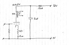
Presents the idea for a series filter CCS to a final shunt capacitor for B supply. The stage runs constant current, plate voltage floats to wherever it floats to, high PSRR and tightly controlled AC signal loop. Seems ideal for inductive loaded stages where Ip interacts with air gap and also sets Rp of the tube. It seems this would also enable the use of 'not so well matched tubes' throughout service life, and without need for adjustment.
For example, and as below; 12uF shunt cap as final element of the B Supply which is sized to avoid resonance between this capacitor and the inductive load at AF and provide LF pole <5Hz.
Is there any obvious consequence to using such a small capacitor with its high impedance, or is this relative to the high series impedance of the CCS and nothing else?.
"..Now that we have effectively removed the power supply loop from the signal output loop, the output signal loop completion is simplified to the PSU bypass capacitor; what value should this capacitor be?
The signal output or load loop is comprised of the stage resistance (already calculated as 2.7 kΩ), the PSU bypass capacitor to ground and then via the cathode bypass capacitor to the cathode. (It should be noted that the PSU capacitor and the cathode bypass capacitor appear in series the consequences of which we examine later.)
The minimum value of the bypass capacitor is given by C = reciprocal (2 x π x f x R).
Again, our lowest frequency of interest of is 5Hz and so we have
Reciprocal (2 x π x 5 x 2.7e3) = 11.78 say 12 µF.
This value is available in high quality film devices; we no longer need to horribly compromise our lovingly created signal path with an electrolytic capacitor."
Last edited:
I would be very cautious about anyone who starts throwing in evocative words near the start to substantiate why any existing setup needs a 'solution'.
The first premise made is that there is audible sonic interaction - based on others experiences - but no assessment of the level of that interaction, just some current path diagrams to make you gasp that there must be an audible interaction.
The next premise is that the input signal current loop is a big ticket item. Then the dialogue moves to the output stage interaction, with evocative language such as 'making matters worse' and identifying current paths that audibly impact sonic results, and limiting potential musical beauty, and severe resonances and disastrous impacts. Then like a storm subsiding, a proposed solution enters from stage left to bring sonic beauty back to valve amps.
A smaller capacitance will have a rising impedance at lower frequency. Performance of an amp for the most basic metrics of HD, IMD, noise floor and hum, and response flatness can fairly easily be diy measured nowadays, so I would recommend anyone with a keeness to at least check those metrics for any circuit change on a particular amplifier circuit and setup.
Evocative words, yet he is writing a blog, and what to do with that?. A bit like your 'Then, like a storm subsiding a proposed solution enters from stage left...". Words. I take your point. And again about measurements. Best I can see is that if resonance is somewhere closer to 1/4 to 1/2 frequency the LF corner, and if that is below 5Hz, all as created by the C and L.. it really brings me back to where I was.
Nothing off-cuff suggests that Xc of a 12uF cap fed by a 2G z.CCS is anything to look at more than once?.
Nothing off-cuff suggests that Xc of a 12uF cap fed by a 2G z.CCS is anything to look at more than once?.
Resonances from L and C parts in a power supply are very much modified from ideal CLC type calculated frequencies by the input forcing and output loading characteristics, and their damping affects along with practical ESR of L.
Its not easy to make a good assessment. Simulation like from PSUD2 and LTSpice go some way to ball-parking a resonant frequency and damping factor. Experimental checking of what happens to an amps output may be much more onerous to assess.
Its not easy to make a good assessment. Simulation like from PSUD2 and LTSpice go some way to ball-parking a resonant frequency and damping factor. Experimental checking of what happens to an amps output may be much more onerous to assess.
Richard and I have been friends for several decades. I have designed a number of amplifiers that use a similar approach to that described in this article. We were both working on the same general approach at the time and came to generally similar conclusions.
This isn't about an "existing setup" it's about a design technique to reduce supply interactions targeting presumably a new design.
All of my current designs are all quite heavily decoupled from the power supply.
He's quite rigorous and analytical in his approach to design, and also tests his ideas in actual physical amplifiers. (Which measure well and sound good in my experience)
He's not necessarily writing for an audience with an engineering background (which is his background) and is also trying to present ideas in an engaging manner.
He's not necessarily writing for an audience with an engineering background (which is his background) and is also trying to present ideas in an engaging manner.
Who doesn't want their B+ to be ripple free especially with.... an air gapped, inductive loaded stage.... sheeeesh. Just say your talking SE. Then he gets to the end and has to say this... ' We no longer need to horribly compromise our lovingly created signal path with an electrolytic capacitor... ' It's just another sales pitch for boutique caps. We can now avoid horrible compromises that create horror... the horror... the compromise... Why?! Oh, why have we had to live like this for so long?!
Last edited:
Richard and I have been friends for several decades. I have designed a number of amplifiers that use a similar approach to that described in this article. We were both working on the same general approach at the time and came to generally similar conclusions.
This isn't about an "existing setup" it's about a design technique to reduce supply interactions targeting presumably a new design.
All of my current designs are all quite heavily decoupled from the power supply.
He's quite rigorous and analytical in his approach to design, and also tests his ideas in actual physical amplifiers. (Which measure well and sound good in my experience)
He's not necessarily writing for an audience with an engineering background (which is his background) and is also trying to present ideas in an engaging manner.
Kevin, thanks for bringing this back on track. Any thoughts as to the importance of Xc of the final shunt element as per the original question?.
Thanks.
Resonances from L and C parts in a power supply are very much modified from ideal CLC type calculated frequencies by the input forcing and output loading characteristics, and their damping affects along with practical ESR of L.
Its not easy to make a good assessment. Simulation like from PSUD2 and LTSpice go some way to ball-parking a resonant frequency and damping factor. Experimental checking of what happens to an amps output may be much more onerous to assess.
The only question I have is WRT the impedance of the shunt capacitor element (Xc), and whether that is important in and of itself, or whether its relevance is purely determined by the series impedance of the filter CCS.
That's better.
If you simply had a constant current input supply, then the main B+ filter cap passes all signal current.
If the average current draw from the output stage changes (as happens in class A, especially when signal peaks increase output power beyond say 30-50%) then B+ will move around according to power balance requirement. If you don't suppress that then distortion would change.
If the main filter B+ cap has a substantial impedance at a frequency the amp is trying to generate a large signal swing for, then the cap impedance becomes non-negligible part of the voltage and phase response of the output stage. The alternate view is that the main cap has a negligible impedance for all signal frequencies that the output stage is amplifying. You could simulate that with LTSpice, or google/search for those who have - doing it yourself would allow a constant current supply to be implemented and comparison results generated.
Is it true that our lowest frequency of interest is 5Hz? Syllabic rates (i.e. envelope rates) in speech and most music are often slower than this, and second-order distortion can create currents at these low rates. Do we want to present such currents with a high impedance supply rail so they can generate voltages?
If a supply rail is supposed to be a voltage supply then it seems to me that it should be fairly low impedance at all frequencies of interest, not just the usual music bandwidth.
I think I am saying the same thing as trobbins.
If a supply rail is supposed to be a voltage supply then it seems to me that it should be fairly low impedance at all frequencies of interest, not just the usual music bandwidth.
I think I am saying the same thing as trobbins.
If you simply had a constant current input supply, then the main B+ filter cap passes all signal current.
If the average current draw from the output stage changes (as happens in class A, especially when signal peaks increase output power beyond say 30-50%) then B+ will move around according to power balance requirement. If you don't suppress that then distortion would change.
If the main filter B+ cap has a substantial impedance at a frequency the amp is trying to generate a large signal swing for, then the cap impedance becomes non-negligible part of the voltage and phase response of the output stage. The alternate view is that the main cap has a negligible impedance for all signal frequencies that the output stage is amplifying. You could simulate that with LTSpice, or google/search for those who have - doing it yourself would allow a constant current supply to be implemented and comparison results generated.
Thanks trobbins and DF96 for being on point here.
Are you meaning that for situations other than a power output stage the substantial impedance of the capacitor should not be a factor, and that small signal voltage gain stages should be less adversely affected (if at all)?
Is it correct to assume that the magnitude of this impedance, so far as it being considered 'substantial' or otherwise, should not be evaluated by comparing directly to the AC impedance of the CCS, but but some other metric? (if so, this answers my question - I was thinking in terms of voltage divider where any impedance of the capacitor is negligible compared with that of the CCS - and thought that might be part of the direction in which the author was headed to/from).
It seems 'substantial' should be determined by the measured effect in circuit. If the same type of supply was used on two successive stages who's signal is 180 out of phase, would the possible effects which you mention simply cancel if the impedance of the two capacitors (one for each supply, stacked DC circuit) were to be the same?
Last edited:
The topic of supply rail bypass capacitance (in a typical RC ladder supply distribution scheme) aligns with motorboating as one observable consequence. Distortion performance from such a stage could also be influenced, but i don't recall seeing lots of references/tests on that.
The metric for supply rail impedance is the circuit stage impedance, typically at the stage output. The ratio between CCS impedance and shunt capacitor impedance is relevant when calculating ripple reduction but irrelevant when considering unwanted circuit coupling or subsonc misbehaviour.
In my view feeding a capacitor via a CCS is a good way to make a bad supply rail. Much better (and simpler, cheaper) to use a resistor. Even better to use a choke.
In my view feeding a capacitor via a CCS is a good way to make a bad supply rail. Much better (and simpler, cheaper) to use a resistor. Even better to use a choke.
Paraphrased, with addendum: In my view, feeding a capacitor with a CCS is a recipe for a convoluted troubleshooting problem. Much better (and simplest) is to use a resistor. Even better to use a choke. And IMHO, the best of all is to use an inexpensive, durable MOSFET series regulator.
Thanks DF96… GoatGuy
Thanks DF96… GoatGuy
The metric for supply rail impedance is the circuit stage impedance, typically at the stage output. The ratio between CCS impedance and shunt capacitor impedance is relevant when calculating ripple reduction but irrelevant when considering unwanted circuit coupling or subsonc misbehaviour.
In my view feeding a capacitor via a CCS is a good way to make a bad supply rail. Much better (and simpler, cheaper) to use a resistor. Even better to use a choke.
Thanks DF96. Is the metric for Xc and circuit stage impedance what Richards calculations work through WRT LF performance (including the subsonic issue and gain peaking at resonance) at the link in the original post?.
I have built a simple grounded cathode circuit with 45H primary transformer, CCS to 33uF shunt cap. Following Richards calculations 10-12uF would have been acceptable if adhering to his 5Hz frequency of interest. There is some LF peaking similar to what you see with a typical CCS loaded parallel feed stage, but less than 3dB and below 5Hz, nothing untoward distortion wise on the scope.
I can appreciate your comment about making a better supply, assuming LF issues are mitigated, can I ask what the 'unwanted circuit coupling', that you mention might be?.
Thanks.
Last edited:
And IMHO, the best of all is to use an inexpensive, durable MOSFET series regulator.
GoatGuy
This thread is just a sales pitch for boutique caps. It's a solution looking for a problem. The first basic design step is to know what power the output needs according to the user's music power requirements then add the front end draw and add some marginal reserve for good measure. That gives the designer all the room he needs to decouple the front end from the backend, and provide all the B+ power the output demands thus.... 'Minimising power supply interaction.' IMHO a few ohms of ESR in a supply that's got some headroom is not a factor in the least considering all the other R in the circuit... DCR of the OPT, plate resistance, supply DCR, line voltage variation, and normal listening levels that are quite under max Pd. ... decoupling, decoupling, decoupling.. is easy. If you want to hammer the B+ with excessive demand, that's on the designer's poor choices.
Last edited:
1. Application is a low level voltage gain stage (150mVpp input) and not a power output stage.
2. Xc of a 12uF cap is more than a few ohms especially at lower frequencies.
3. I wish to pursue this as it provides some flexibility/options which suit my application.
4. I'm not selling caps, so you can leave that one at home.
From what I'm gathering its better to leave the value of capacitance at some higher value in order to present a lower impedance for the reasons that DF96 mentions above. I cant see a problem with the series CCS if LF issues are mitigated, but curious as to the potential unwanted coupling as per comment above.
Last edited:
1. Application is a low level voltage gain stage (150mVpp input) and not a power output stage.
2. Xc of a 12uF cap is more than a few ohms especially at lower frequencies.
> 4. I'm not selling caps, so you can leave that one at home.
So the supply voltage at the filter then goes through the plate load resistor normally in the 50K to 200K range to the plate... is 5 ohms in series going to matter? What ESR are you working to avoid? The quoted reference in post #1 was selling caps.
Okay with quoted reference but think to give him benefit of the doubt, after all it cost me nothing to read his blog and I'm free to choose my own capacitor.
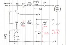
WRT ESR question, a drawing might be easier; my question/concern relates to the impedance of the capacitor.
Cheers.
WRT ESR question, a drawing might be easier; my question/concern relates to the impedance of the capacitor.
Cheers.
Attachments
Last edited:
WRT ESR question, a drawing might be easier; my question/concern relates to the impedance of the capacitor.
Cheers.
Is cap ESR ever part of the Cx or the C...impedance, for resonant frequency or poles calculations? I've just never heard of it. But that's just me.. Hanze, I think in this case you're the pioneer. If you're just looking for the right sized cap to go with the choke load for best LF filtering, I will defer to the prior formulas and wish you find the best fit for your objective. I believe the math will out. Good luck with the project. Go Sixers!
Classical approach is to reduce actual circuit to equivalent circuit.
For a constant signal level, could remove constant current supply, and replace the filter cap as a voltage source in series with a resistor, as a model for when average power consumption doesn't change. You could then simulate or experimentally measure the change in output signal distortion with change in capacitor ESR. I think that is the outcome you are trying to get some insight on.
For a varying signal level, and assuming your constant current source stayed constant, and assuming the signal stepped between a low and a high level, then that could be modelled by an added voltage source that has a constant dV/dt ramp between 2 voltage levels - assuming the average current drawn for the two signal levels are different due to typical class A operation. The added voltage source may not be large for a triode operating class A, but is noticeable for a pentode or pentode strapped as triode in a PP output stage.
- Status
- This old topic is closed. If you want to reopen this topic, contact a moderator using the "Report Post" button.
- Home
- Amplifiers
- Tubes / Valves
- R. Sears - Minimising Power Supply Interaction