I have just put a new ecl86 valve in my Kreisler 11-102 hi fi amp. So that means 3 old ones with 1 new one.Two valves share one cathode bias resistor and cap. I was curious if I should now use 4 separate resistors ,I think double the ohms and halve the watts. If I do that I was wondering what do I do with the shared 25 mf cap, halve it, double it, or duplicate it? Any suggestions?
Yes, if you change from two 180R cathode resistors to 4, it needs to be 360R. I would keep the bypass cap at 25uf. This will increase the low end cut off frequency. But if you want to keep the original cut off frequency (ie: to help keep the opt from saturation), use near 1/2 of 25uf.
... I was curious if I should now use 4 separate resistors, I think double the ohms and halve the watts. If I do that I was wondering what do I do with the shared 25 mf cap, halve it, double it, or duplicate it? Any suggestions?
Yes if each valve has individual resistors, double their resistance value. I would suggest 2 or 3 watt.
Then each resistor (valve) will need it's own by-pass cap. The original value will be fine. Just put 4 new ones in.
To find frequency cutoff use this formula - 1/ (2 * pi * R * C) or substitute f for either R or C. R is in ohms, EG 5k6 = 5600, C is in farads, so 22u = 0.000022. You can just use 6.28 instead of 2 x pi. So a 22u and 360r will give about 15hz cutoff, the next down value is 10u gives you a cutoff of around 44hz. Most electrolytics have a tolerance of -10 to +20 or 50% anyway, so actual cutoff is ish.
One other aspect to look at is cap DC bias voltage, a cap used as a cathode bypass cap will have a low DC voltage on it, from 1v to 14v say, try and get a cap with a similar low rating, no good using a 63v rated cap. Tantalum's are good here unless your worried about them going SC, have never had any problems though.
Andy.
Two things wrong with the information you have been given:
1. The LF rolloff does not occur when the capacitor reactance is equal to the cathode resistor, but when the capacitor reactance is equal to the parallel combination of cathode resistor and cathode impedance (approximately 1/gm). Hence the rolloff will be higher than calculated above. You probably need twice the value calculated above.
2. The original circuit with a shared resistor meant that the signal current in the push-pull output will roughly cancel, especially at LF, so it would work reasonably well without a capacitor at all. The capacitor has most effect at higher frequencies where drive may become a bit unbalanced due to stray capacitance etc. With individual resistors and bypasses you get all the current so need good bypassing. You need a bigger cap.
In addition:
3. Another issue not mentioned so far is that in order to avoid any problems with capacitor distortion it is usual to size an electrolytic in the signal path at about 10 times the value needed for a given LF rolloff i.e. don't let the cap set the rolloff.
Putting all this together, if you go from 25uF joint cap I would put 100-220uF individual cap.
I have just put a new ecl86 valve in my Kreisler 11-102 hi fi amp. Two valves share one cathode bias resistor and cap. I was curious if I should now use 4 separate resistors , Any suggestions?
Don't change anything, just measure the cathode current through your pair with the new tube and see if it is still in the expected range. You may want to re-pair them with one from the other channel if you think the balance is off, but if it's off much you ought to be getting a second new tube to pair with the fresh one.
... Another issue not mentioned so far is that in order to avoid any problems with capacitor distortion it is usual to size an electrolytic in the signal path at about 10 times the value needed for a given LF rolloff i.e. don't let the cap set the rolloff.
Putting all this together, if you go from 25uF joint cap I would put 100-220uF individual cap.
Out of interest, in the real world situation, with say 25 or 50uF caps, what will the OP notice? After all there are quite a few amplifiers with those values fitted originally especially console types.
20to20, that is a fair take.
But if the OP fits the 4 individual resistors and measures each cathode voltage in turn he can find the best matching pairs.
Then he has the choice, run with individual resistors or strap the cathode pairs back together as 'original'.
20to20, that is a fair take.
But if the OP fits the 4 individual resistors and measures each cathode voltage in turn he can find the best matching pairs.
Then he has the choice, run with individual resistors or strap the cathode pairs back together as 'original'.
There are so many ..but ifs.. in this hobby. If the 4 tubes are given their own Rk then ..if.. you want a cleaner output you can toss the bypass caps and use the local FB on the K. The bypass caps are only necessary with shared a Rk. Lose a little gain, maybe improve the distortion out.
What if?......
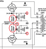
Keep the common resistor but put in small ones for each tube as shown in the attached circuit. (It's from the ongoing Japanese DIY circuits posted on this forum.)
At least then the current draw of individual tubes could be calculated by measuring the voltage drop at measurement points A-B versus C-B.
Steve
Attachments
Keep the common resistor but put in small ones for each tube as shown in the attached circuit. (It's from the ongoing Japanese DIY circuits posted on this forum.)
At least then the current draw of individual tubes could be calculated by measuring the voltage drop at measurement points A-B versus C-B.
Steve
Or you could test across the cathodes (A-C) and look for 0V for a matched pair (one measurement is easier than two, the lower the voltage, the better the match) and without having to spend as much for higher power resistors and extra caps.
Last edited:
- Status
- This old topic is closed. If you want to reopen this topic, contact a moderator using the "Report Post" button.
- Home
- Amplifiers
- Tubes / Valves
- Cathode bias caps