Hi,
I just finished a el84,ecc88 pushpull amp using a pcb from ebay. I had most of the parts so I thought I'd give it a go. It works but has a bad hum that gets louder with more volume the turns into a loud buzz, then starts pulsing faster. I have the schematic and if anyone can help me fix the noise it'd be great.
THANKS
Attachments
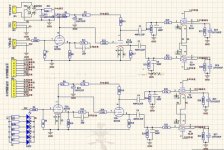
Why are the input tubes grid stopper resistors on the wrong side of the grid leak resistor?
Grid stoppers belong to be connected directly to the grid tab of the tube socket.
Do not connect anything else to the grid tab.
Instead connect the rest of the circuits 'Through the grid stopper resistor' on their way to the grid.
Grid stoppers belong to be connected directly to the grid tab of the tube socket.
Do not connect anything else to the grid tab.
Instead connect the rest of the circuits 'Through the grid stopper resistor' on their way to the grid.
1. 6A3sUMMER you are right, it is week voltage divider.
2.Second thing I see is that someone use both halfs of ECC88 tube for 1st and 2nd stage of amplification. As I remember it is a bad thing to do. I always use one whole tube for 1st stage and 2nd tube for 2nd stage of amplification. See some schematics on google...
3.Before R34 and R33 are missing a 1M pull down resistors like R7
4. At the end you can try with bigger capacitance in high voltage PSU, maybe your high voltage isn't stabilized enough.
Is your heater supply definitely grounded?Hi,
It works but has a bad hum that gets louder with more volume the turns into a loud buzz,
Thanks for you help, I don't know which resistors are the gridstop ones, I just solder the boards together .Do I just remove these resistors? The heater supply is earthed.I disconnected the NFB in case that was wrong but it made no difference. This was a cheap pcb so I still have all the bits.
The phase splitter is DC coupled to the first stage, so no grid leak resistor is needed and it should not be added.Pucur said:3.Before R34 and R33 are missing a 1M pull down resistors like R7
The circuit is very badly drawn, which may indicate that it was badly designed.
I am going to guess that you have parasitic oscillation in the first stage. Putting the grid stopper in the right place may cure it. The grid stopper is the resistor in series with the grid (e.g. R5).
Agreed. One could bare read something. And what's the purpose of this LED-resistors-with-no-external-connection arrangement at the lower left hand corner?The circuit is very badly drawn, which may indicate that it was badly designed.
Best regards!
Agreed. One could bare read something. And what's the purpose of this LED-resistors-with-no-external-connection arrangement at the lower left hand corner?
Best regards!
Six LEDs and six valves, maybe cosmetic purpose?
Supposedly not at all. 'Cause without being fed they simply won't do anything.
Best regards!
If you take the trouble to read more carefully, you will see that LEDs/Resistors array is connected between H1 and H2, supposedly heater voltage.
Some people like the glow of a blue LED under the valve.
I'll pass, thank you.
- Status
- This old topic is closed. If you want to reopen this topic, contact a moderator using the "Report Post" button.
- Home
- Amplifiers
- Tubes / Valves
- EL84 ECC88 pp pcb