I'm investigating the possibility of doing a LW style amp with an EL34 for the output stage. I have a pair of Transcendar 5k:8/4 7W OTs that are somewhat under utilized in their current project as well as an Antek AS-1T200 for power. The OT's can only handle 75mA, and 5K is a bit high for the 375v voltage in most datasheets (For SE triode), but going up to 400v looks like a good fit at 5k for about 7W. With the primaries in series the Antek should do about 565 @ 150mA. I'm thinking I drop about 140v across the cathode circuit to power a single triode stage (either ECC99 or E88CC) with a choke load. TubeCad has an article I pillaged all the basics from:
Loftin-White Amplifier
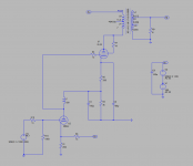
Attached is a screen shot of my current plan. About 60ish mA of bias current (max), a 3k cathode resistor (Dissipates a hefty 6W) and a 1k 2W bias pot (currently set to 350 ohms in the screen shot). The idea being that the voltage drop across the pot (trim-able) plus the drop across the DCR of the choke (fixed with bias current of the preamp stage) sets the -Vgk at the grid. The EL34 cathode current minus whatever gets diverted for the preamp stage sets the drop across the 3K, which becomes the preamp stage's supply.
I'm still shopping for a choke. I suspect I'll end up with a Lundahl from the LL1668 series. There's an outside chance I try a CCS version but for now I like the idea of trying a choke.
I didn't start out planning a DC coupled amp, it's just that the parts I have seem to work out just right. Thoughts?
Loftin-White Amplifier
Attached is a screen shot of my current plan. About 60ish mA of bias current (max), a 3k cathode resistor (Dissipates a hefty 6W) and a 1k 2W bias pot (currently set to 350 ohms in the screen shot). The idea being that the voltage drop across the pot (trim-able) plus the drop across the DCR of the choke (fixed with bias current of the preamp stage) sets the -Vgk at the grid. The EL34 cathode current minus whatever gets diverted for the preamp stage sets the drop across the 3K, which becomes the preamp stage's supply.
I'm still shopping for a choke. I suspect I'll end up with a Lundahl from the LL1668 series. There's an outside chance I try a CCS version but for now I like the idea of trying a choke.
I didn't start out planning a DC coupled amp, it's just that the parts I have seem to work out just right. Thoughts?
Attachments
The idea looks good.
I will not take the time to check your DC levels.
That circuit should work if you get the DC right.
. . . But I did notice one thing:
You put R13 on the wrong side of R10. Grid stopper resistors belong connected directly to the grid tab of the tube socket, with Nothing else connected to the grid tab (otherwise the grid stopper can not do its work).
Here are some further insights from simulation.
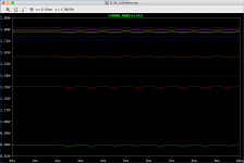
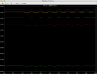
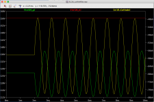
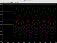
One thing that worried me was burning up the potentiometer under some combinations of settings. While a pot that can handle some power is necessary it looks like a 2W should be OK. The first two attachments show dissipation when the pot is varied between 100 and 900 ohms with 0, 680, and 1500 ohms of choke DCR. The DCR matters because the choke will drop some of the bias voltage - a magical 0 ohm choke would put the greatest burden on the potentiometer.
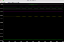
The 4th screen shot is anode current over the same spread of values assuming a 680 ohm choke. The range looks good.
Last are the DC levels at the grid and cathode along with Anode current.
One thing that worried me was burning up the potentiometer under some combinations of settings. While a pot that can handle some power is necessary it looks like a 2W should be OK. The first two attachments show dissipation when the pot is varied between 100 and 900 ohms with 0, 680, and 1500 ohms of choke DCR. The DCR matters because the choke will drop some of the bias voltage - a magical 0 ohm choke would put the greatest burden on the potentiometer.
The 4th screen shot is anode current over the same spread of values assuming a 680 ohm choke. The range looks good.
Last are the DC levels at the grid and cathode along with Anode current.
Attachments
This is not Loftin& White . You have invented a new circuit . I love it .
I wish! Check out the TubeCad link and read up on improvements to the LW topology.
Just a quick check in: I wired up my PT as a test, and I’m glad I did because with no load my B+ came in a bit lower than expected. Under load it will be even lower than that so I think I’ll be starting from about 520v rather than 560. I’ve ordered a few different sizes of cathode resistor so I can tune a bit. I also placed an order for 100H inductors. The dcr is a bit higher than I’d hoped but it really only matters in the preamp tube fails or is removed and I expect it would only change the bias by about 20%. I’m going to try and get a prototype wired up (sans chokes) in the next week or so.
Electraprint’s schematic is dated 2007. There is a TubeCad article linked inside of the one I linked, published in May 2000, that shows this configuration. Regardless, it seems unlikely that no one dropped a choke in a LW amp before either of them.
The Tube Cad Journal: Design Idea-A safe Loftin-White amplifier
The Tube Cad Journal: Design Idea-A safe Loftin-White amplifier
Last edited:
My version of LF with Choke load from 2017: GU15 SE amp prototype
and my PushPull version: 6C4C in PP (Loftin White)
Both are one of the best sounding amps I have heard ever. Now I am planing to build PP version with 300B tubes.
and my PushPull version: 6C4C in PP (Loftin White)
Both are one of the best sounding amps I have heard ever. Now I am planing to build PP version with 300B tubes.


That's good to hear. How long have they been in service? It looks like you derive your -Vgk from the voltage drop across the inductor's DCR. The preamp is running at 8.6mA so you have a ~24v drop from the GU15T's cathode to it's grid. Did you have to tune R9? Where did you buy your inductors?
Hi, I did not tune R9. Somehow it works good from begining. GU15 is in service for about 300 hours and 6C4C for 30 hours.
Chokes are from there: Anodendrosseln, Choke 62.15 - Anodendrossel 150H / 600H, bis 20/10mA, ca. 3000/12000 Ohm 130 / 55 pF.
Chokes are from there: Anodendrosseln, Choke 62.15 - Anodendrossel 150H / 600H, bis 20/10mA, ca. 3000/12000 Ohm 130 / 55 pF.
PRR,
Good printed example. Thanks!
A lot of leading research and development was also done by Radio Amateurs.
Then there was Mr Heil, the inventor of the Heil air motion tweeter. He had plans for an FET, but it was before there was the solid state technology to support it. His on-paper FET was before Bell Labs came up with the Point Contact Transistor.
"Those who do not know the history of early inventions are bound to repeat them." (stolen and re-worded by me)
Last edited:
Hi, I did not tune R9. Somehow it works good from begining.
It’s nice when things work out!
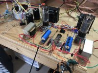
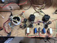
Ok! Prototype is done! Pictures attached. Sounds nice so far but I’ll do some more demanding listening test today. Currently there is no feedback and the e88cc cathodes are unbiased. I’m running the outputs cool for now too, about 20W.
Attachments
Last edited:
- Status
- This old topic is closed. If you want to reopen this topic, contact a moderator using the "Report Post" button.
- Home
- Amplifiers
- Tubes / Valves
- A Loftin-White style SE with EL34