Hi,
I want to build this tube amp, have some of the parts but before dedicating my time to it I have some questions about the schematic.

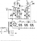
First of all, I managed to get my hands on that 3k output transformer BUT according to the website below the voltage or the impedance won't match with the EL34 specs.
The Valve Wizard -Single Ended
(I think I found this valve wizard website around here)
If we go by the schematic and calculate it, it says that for 25W anode dissipation of the EL34 and 320V supplied I should use 4k transformer instead of 3k. Is this correct?
Another thing surrounding the EL34, there is no screen resistor and mostly in other schematics and designs, I've seen one. Why is that here?
Now I wasn't able to find the preamp EF86 tubes but instead, I have found EF37A ones. As I've read in two datasheets, it says that maximum voltage for g2 is 140V for EF86 and 100V for EF37A. My question is, can I freely substitute these two because in one of the datasheets the data provided is for both tubes.
By me, I think I should change the R4 resistor to lower the voltage to around 100V.
I have only 4 tubes, 2xEF37A and 2xEL34.
I want to build this tube amp, have some of the parts but before dedicating my time to it I have some questions about the schematic.
First of all, I managed to get my hands on that 3k output transformer BUT according to the website below the voltage or the impedance won't match with the EL34 specs.
The Valve Wizard -Single Ended
(I think I found this valve wizard website around here)
If we go by the schematic and calculate it, it says that for 25W anode dissipation of the EL34 and 320V supplied I should use 4k transformer instead of 3k. Is this correct?
Another thing surrounding the EL34, there is no screen resistor and mostly in other schematics and designs, I've seen one. Why is that here?
Now I wasn't able to find the preamp EF86 tubes but instead, I have found EF37A ones. As I've read in two datasheets, it says that maximum voltage for g2 is 140V for EF86 and 100V for EF37A. My question is, can I freely substitute these two because in one of the datasheets the data provided is for both tubes.
By me, I think I should change the R4 resistor to lower the voltage to around 100V.
I have only 4 tubes, 2xEF37A and 2xEL34.
Another thing surrounding the EL34, there is no screen resistor and mostly in other schematics and designs, I've seen one. Why is that here?
The screen grid in EL34s is reasonably tough (see all the UL mode setups). 300 V. on both the plate and screen seems safe enough.
I'm curious as to why this design was attractive. Asking the sonicly nice, but wimpy, EF86 to drive the CMiller of a triode wired EL34 is a prescription for HF info. loss. DC heaters in a power amp is an unnecessary frill. IMO, the wrong details were focused on.
Decide what you want.
For that circuit, the EL34 has about 56mA, 276Vp-k, and 15.4 Watts plate + screen dissipation. The plate resistance is about 1300 Ohms, 3k load gives a damping factor of about 2.3 or less, which increases when you apply the negative feedback.
A question to ask is: With negative feedback, will the circuit be stable with the output transformer you use? (anything other than the exact transformer it was designed for and tested to work properly with).
Also, please note that the Valve Wizard - Single Ended reference you linked to was for Pentode wired EL34 tubes. Your circuit is for Triode wired EL34 tubes.
Last edited:
First of all, I managed to get my hands on that 3k output transformer BUT according to the website below the voltage or the impedance won't match with the EL34 specs.
The Valve Wizard -Single Ended
(I think I found this valve wizard website around here)
Well, technically you would have ~275v for a plate voltage. You need to subtract off the losses in the OT and the raised cathode voltage. Most importantly, you can never get any of these factors perfect anyway so don’t fret about +/-10% on the more difficult to control items.
Now I wasn't able to find the preamp EF86 tubes but instead, I have found EF37A ones. As I've read in two datasheets, it says that maximum voltage for g2 is 140V for EF86 and 100V for EF37A. My question is, can I freely substitute these two because in one of the datasheets the data provided is for both tubes.
By me, I think I should change the R4 resistor to lower the voltage to around 100V.
EF86 and EF87 are either pin nor electrically compatible. Beside changing the pin connections, you will need to adjust the circuit a little to make it work. They are similar enough, the changes needed are small. The G2 voltages you listed are suggested operating value and not maximum value. Both tubes can handle 400V+ G2. The I/V curve (u and gm) are different between the two tube.
I would suggest, running the EF87 G2 at 150V to minimize the circuit changes. With that, run the grid bias at -2.5V and Ip to 2.1mA. You can achieve that by changing the cathode resistor to 2.4K or so. Adjust it until you get -2.5V bias.
Anyone notice the essentially dead short across both secondary windings, on the diode bridges….
Hmmm
Until you mentioned it I hadn't noticed, but the symbol could just say "bridge" and I'd connect it correctly. The AC goes in where the DC is supposed to come out
")
The 680k grid resistor may be too much for an EL34. The datasheet says 500k max, although it does not specify under what conditions.
This circuit is a mix of unnecessary things (such as DC heaters) and unfortunate things (EF86 driving a triode EL34). It has bypasses on the reservoir and smoothing caps (unnecessary, although hopefully not too harmful) yet uses 1N4007 so could suffer from reverse recovery noise. I am unclear what the neutralisation(?) around the EF86 is supposed to do - compensate for poor layout, perhaps?
Was this design by the same Rainer Linde who wrote a rather strange book on valve audio? The reviews on Amazon do not provoke confidence!
DC heaters in a power amp is an unnecessary frill. IMO, the wrong details were focused on.
In my experience of valve amp design I have never found DC heaters to help with noise. I have always found the noise came from other sources like poor layout or interference between transformers and circuit.
Beware both bridge rectifiers are draw wrong. Rotate both 90 degrees clockwise.
Last edited:
The screen grid in EL34s is reasonably tough (see all the UL mode setups). 300 V. on both the plate and screen seems safe enough.
I'm curious as to why this design was attractive. Asking the sonicly nice, but wimpy, EF86 to drive the CMiller of a triode wired EL34 is a prescription for HF info. loss. DC heaters in a power amp is an unnecessary frill. IMO, the wrong details were focused on.
Thanks for answering. Actually I'm not very "fixed" on this design, just wanted to build something simple with couple of tubes that will atleast drive a speaker set instead of headphones. Also I had already the tubes in my drawer.
But feel free to suggest me some other design with ef37/el34.
Thanks for the explanation. You are correct, that website post is for pentode designs. I have honestly just slid through the text and read more on the formulas....Decide what you want.
For that circuit, the EL34 has about 56mA, 276Vp-k, and 15.4 Watts plate + screen dissipation. The plate resistance is about 1300 Ohms, 3k load gives a damping factor of about 2.3 or less, which increases when you apply the negative feedback.
A question to ask is: With negative feedback, will the circuit be stable with the output transformer you use? (anything other than the exact transformer it was designed for and tested to work properly with).
Also, please note that the Valve Wizard - Single Ended reference you linked to was for Pentode wired EL34 tubes. Your circuit is for Triode wired EL34 tubes.
Hmm, now that you mention it. Can one tube be driven on DC heater voltage and the other on AC? Because now looking at it the output of the regulator it only states connection to the V1 and that's the EL86 tube, but not the EL34. Maybe the EL34 needs AC?Anyone notice the essentially dead short across both secondary windings, on the diode bridges….
Hmmm
Hmmm I don't know if you mixed them up, but I have EF37A not EF87, or is just a typo and your data shared is correct.EF86 and EF87 are either pin nor electrically compatible. Beside changing the pin connections, you will need to adjust the circuit a little to make it work. They are similar enough, the changes needed are small. The G2 voltages you listed are suggested operating value and not maximum value. Both tubes can handle 400V+ G2. The I/V curve (u and gm) are different between the two tube.
I would suggest, running the EF87 G2 at 150V to minimize the circuit changes. With that, run the grid bias at -2.5V and Ip to 2.1mA. You can achieve that by changing the cathode resistor to 2.4K or so. Adjust it until you get -2.5V bias.
I think the AC or the "bridge" is the heater for EL34, or maybe not..Until you mentioned it I hadn't noticed, but the symbol could just say "bridge" and I'd connect it correctly. The AC goes in where the DC is supposed to come out
Yes I think that's the book, although I found the schematic here EL34 Single-Ended (SE) Tube Amplifier Schematic EL-34The 680k grid resistor may be too much for an EL34. The datasheet says 500k max, although it does not specify under what conditions.
This circuit is a mix of unnecessary things (such as DC heaters) and unfortunate things (EF86 driving a triode EL34). It has bypasses on the reservoir and smoothing caps (unnecessary, although hopefully not too harmful) yet uses 1N4007 so could suffer from reverse recovery noise. I am unclear what the neutralisation(?) around the EF86 is supposed to do - compensate for poor layout, perhaps?
Was this design by the same Rainer Linde who wrote a rather strange book on valve audio? The reviews on Amazon do not provoke confidence!
Thanks for the heads up, although I wanted to use premade bridge rectifiers instead of the listed 1A diodes.In my experience of valve amp design I have never found DC heaters to help with noise. I have always found the noise came from other sources like poor layout or interference between transformers and circuit.
Beware both bridge rectifiers are draw wrong. Rotate both 90 degrees clockwise.
Hmmm I don't know if you mixed them up, but I have EF37A not EF87, or is just a typo and your data shared is correct.
Typo. I mean EF37 not 87.
Thanks for the explanation. You are correct, that website post is for pentode designs. I have honestly just slid through the text and read more on the formulas....
Another diagram anomaly is the G3/K connection shown internally to the EL34. Not there in those tubes. Has to be added to the socket.
As drawn, that would make for a pretty "exciting" initial power up!
I would say so - oh boy ! I realize it is a simple drawing error. And an actual single package bridge, observing the ac and the plus/minus connections - there would not be an issue...
Someone very new to building the circuit might try to connect individual diodes as shown - then the main fuse will certainly pop...
Carry on !
I'm not new to building circuits, I will surely build it properly and not blindly by the schematic.
Another question, as some suggested that there is no need for DC circuit for the heaters. Then should I drive the tubes on AC only?
Also, I've seen in some circuits that have added soft start both for heaters and/or the anode, does this make any difference for the tubes?
EDIT: Forgot to say, I want to add an EMI filter before the HV transformer should this be enough?
Last edited:
Typo. I mean EF37 not 87.
Alright, so I will need to increase the G2 voltage to about 150V(will 470k be okay?), and increase the resistor and also the grid bias to -2.5V and 2.4K respectively. Are those the only changes needed for this circuit to work with EF37A?EF86 and EF87 are either pin nor electrically compatible. Beside changing the pin connections, you will need to adjust the circuit a little to make it work. They are similar enough, the changes needed are small. The G2 voltages you listed are suggested operating value and not maximum value. Both tubes can handle 400V+ G2. The I/V curve (u and gm) are different between the two tube.
I would suggest, running the EF87 G2 at 150V to minimize the circuit changes. With that, run the grid bias at -2.5V and Ip to 2.1mA. You can achieve that by changing the cathode resistor to 2.4K or so. Adjust it until you get -2.5V bias.
I've mocked up the schematic a bit for the listed changes:
I will drive the heaters on AC so I removed the DC part.
Fixed the bridge, and have adjusted the values for the resistors for EF37
Attachments
- Status
- This old topic is closed. If you want to reopen this topic, contact a moderator using the "Report Post" button.
- Home
- Amplifiers
- Tubes / Valves
- SE EL34 schematic questions