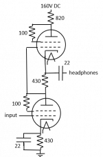
Over the weekend I built a headphone amp based on “The Optimized SRPP Amp” by Blencowe. I emulated the unbypassed version in Part 2, so there is (was) no cap bypassing the cathode resistor.
http://www.valvewizard.co.uk/SRPP_Blencowe.pdf
My intent was to amplify the speaker output of a phone or tablet to drive higher quality headphones, so little gain is required.
I used 600 Ohm headphones, as OTL amps historically like high loads (like the old Phillips OTL totem-pole) and Blencowe points out that this amp likes loads which approach the plate resistance.
6C33C OTL
I used 26E6 tubes (the military version of the 6Y6) for four reasons:
1. When triode-strapped the plate resistance approaches the 600 Ohm load. The plate resistance of triode-strapped pentodes seem to consistently be lower than true triodes, and the 6Y6 was the lowest I found.
2. The heater to cathode voltage tolerance is very large, so I could use a simple heater circuit for both tubes in the totem-pole in spite of the elevated cathode voltage of the “upper” tube.
3. The expected quiescent current of .046 amps is comfortably in the range of the tube
4. I had several of them lying about
http://electronbin.com/sheets/137/6/6Y6GA.pdf
https://frank.pocnet.net/sheets/127/6/6Y6GA.pdf
https://frank.pocnet.net/sheets/087/2/26E6WG.pdf
Note page 3 of the first data sheet for triode characteristics.
Note page 3 of the second data sheet for distortion curves. The curves will shift to the left as B+ is reduced from 200V in the chart to the 80V (half of the 160v for the totem) so I guess the distortion is roughly equivalent to the 1200 Ohm load? If so the 3rd harmonic would be very low, and the 2 second harmonic would be over 15%, except that this is a push-pull circuit which would cancel the 2rd.
The 3rd data sheet is for the military version. Hopefully I do not need the tube’s capability to resist 600G acceleration...
The results of the amp are mixed, and I have only identified some of my mistakes…
My oscilloscope is angry, so I tested the amp subjectively. It sounded wonderful, but lacking in bass. Using a sine wave generator (by ear) it appeared that the output rolled off below about 100 Hz, so I added a bypassing cap in spite of having attempted to use the design for an unbypassed amp. The cap worked and it now has bass. I intended to build the un-bypassed version hoping to retain some of the warmth of the 2nd harmonic, but it sounds almost too clean, perhaps indicating that P-P is cancelling the 2rd harmonic, and the low load is generating little of the 3rd.
However adding the cap did not help the volume. Maximum volume is not much beyond “easy-listening”. Changing B+ from 160V to 380V had no audible impact on volume, so I assume that voltage gain of the input signal is inadequate. Blencowe points out that while the SRPP looks a bit like a cathode follower that it can in fact provide gain. However my calculation predicts a voltage gain of only .6. Substituting the plate resistance and gain of other tubes into the Excel sheet provided even lower gains.
Are my expectations of the circuit unreasonable? Should I use a resistance coupled voltage amp in advance of the SRPP?
Or are my expectations reasonable but my execution flawed?
Are any specific tests are suggested once I repair or replace my old oscilloscope?
http://www.valvewizard.co.uk/SRPP_Blencowe.pdf
My intent was to amplify the speaker output of a phone or tablet to drive higher quality headphones, so little gain is required.
I used 600 Ohm headphones, as OTL amps historically like high loads (like the old Phillips OTL totem-pole) and Blencowe points out that this amp likes loads which approach the plate resistance.
6C33C OTL
I used 26E6 tubes (the military version of the 6Y6) for four reasons:
1. When triode-strapped the plate resistance approaches the 600 Ohm load. The plate resistance of triode-strapped pentodes seem to consistently be lower than true triodes, and the 6Y6 was the lowest I found.
2. The heater to cathode voltage tolerance is very large, so I could use a simple heater circuit for both tubes in the totem-pole in spite of the elevated cathode voltage of the “upper” tube.
3. The expected quiescent current of .046 amps is comfortably in the range of the tube
4. I had several of them lying about
http://electronbin.com/sheets/137/6/6Y6GA.pdf
https://frank.pocnet.net/sheets/127/6/6Y6GA.pdf
https://frank.pocnet.net/sheets/087/2/26E6WG.pdf
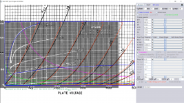
Note page 3 of the first data sheet for triode characteristics.
Note page 3 of the second data sheet for distortion curves. The curves will shift to the left as B+ is reduced from 200V in the chart to the 80V (half of the 160v for the totem) so I guess the distortion is roughly equivalent to the 1200 Ohm load? If so the 3rd harmonic would be very low, and the 2 second harmonic would be over 15%, except that this is a push-pull circuit which would cancel the 2rd.
The 3rd data sheet is for the military version. Hopefully I do not need the tube’s capability to resist 600G acceleration...
The results of the amp are mixed, and I have only identified some of my mistakes…
My oscilloscope is angry, so I tested the amp subjectively. It sounded wonderful, but lacking in bass. Using a sine wave generator (by ear) it appeared that the output rolled off below about 100 Hz, so I added a bypassing cap in spite of having attempted to use the design for an unbypassed amp. The cap worked and it now has bass. I intended to build the un-bypassed version hoping to retain some of the warmth of the 2nd harmonic, but it sounds almost too clean, perhaps indicating that P-P is cancelling the 2rd harmonic, and the low load is generating little of the 3rd.
However adding the cap did not help the volume. Maximum volume is not much beyond “easy-listening”. Changing B+ from 160V to 380V had no audible impact on volume, so I assume that voltage gain of the input signal is inadequate. Blencowe points out that while the SRPP looks a bit like a cathode follower that it can in fact provide gain. However my calculation predicts a voltage gain of only .6. Substituting the plate resistance and gain of other tubes into the Excel sheet provided even lower gains.
Are my expectations of the circuit unreasonable? Should I use a resistance coupled voltage amp in advance of the SRPP?
Or are my expectations reasonable but my execution flawed?
Are any specific tests are suggested once I repair or replace my old oscilloscope?
Attachments
The value of cathode resistor bypass cap should be about 1000uf and output cap about 220uf. For only 22uf the lower end response is poor but ok if you omit it, the response would be flat except the gain is lesser. Triode connected 6y6 has Mu about 7.5, so the gain should be > 1, unless the load is < 100 ohms, the gain then fall to 0.6 or so. If the load is 600 ohms the gain is about 2+. I post 6y6 model here for those interested to model your sch to see the details.
Code:
**** 6Y6GA ******************************************
* Created on 01/15/2019 21:48 using paint_kip.jar
* [URL="http://www.dmitrynizh.com/tubeparams_image.htm"]Model Paint Tools: Trace Tube Parameters over Plate Curves, Interactively[/URL]
* Plate Curves image file: 6y6ga.png
* Data source link: <plate curves URL>
*----------------------------------------------------------------------------------
.SUBCKT 6Y6GA P G2 G K ; LTSpice tetrode.asy pinout
* .SUBCKT 6Y6GA P G K G2 ; Koren Pentode Pspice pinout
+ PARAMS: MU=7.425 KG1=892.51 KP=20.97 KVB=21.24 VCT=1.946 EX=1.339 KG2=3319.68 KNEE=19.14 KVC=1.915
+ KLAMG=5.285E-4   KNK=-0.044 KNG=0.006 KNPL=50 KNSL=11 KNPR=120 KNSR=29
+ CCG=3P CGP=1.4P CCP=1.9P RGI=2000.0
* Vp_MAX=500 Ip_MAX=200 Vg_step=15 Vg_start=0 Vg_count=22
* X_MIN=40 Y_MIN=158 X_SIZE=1084 Y_SIZE=536 FSZ_X=1550 FSZ_Y=878 XYGrid=false
* Rp=1400 Vg_ac=20 P_max=12.5 Vg_qui=-157.5 Vp_qui=300
* showLoadLine=n showIp=y isDHP=n isPP=n isAsymPP=n isUL=n showDissipLimit=y
* showIg1=n isInputSnapped=y addLocalNFB=n
* XYProjections=n harmonicPlot=y dissipPlot=n
* UL=0.43 EG2=135 gridLevel2=n addKink=y isTanhKnee=n advSigmoid=n
*----------------------------------------------------------------------------------
RE1  7 0  1G    ; DUMMY SO NODE 7 HAS 2 CONNECTIONS
E1   7 0  VALUE=  ; E1 BREAKS UP LONG EQUATION FOR G1.
+{V(G2,K)/KP*LOG(1+EXP((1/MU+(VCT+V(G,K))/SQRT(KVB+V(G2,K)*V(G2,K)))*KP))}
RE2  6 0  1G    ; DUMMY SO NODE 6 HAS 2 CONNECTIONS
E2  6 0  VALUE={(PWR(V(7),EX)+PWRS(V(7),EX))} ; Kg1 times KIT current
RE21 21 0 1
E21  21 0 VALUE={V(6)/KG1*ATAN(V(P,K)/KNEE)} ; Ip with knee but no slope and no kink
RE22 22 0 1 ; E22: kink curr deviation for plate
E22  22 0 VALUE={V(21)*LIMIT(KNK-V(G,K)*KNG,0,0.3)*(-ATAN((V(P,K)-KNPL)/KNSL)+ATAN((V(P,K)-KNPR)/KNSR))}
G1   P  K  VALUE={V(21)*(1+KLAMG*V(P,K)) + V(22)}
* Alexander Gurskii screen current, see audioXpress 2/2011, with slope and kink added
RE43 43 K 1G ; Dummy
E43  43 G2 VALUE={0} ; Dummy
G2   43 K  VALUE={V(6)/KG2*(KVC-ATAN(V(P,K)/KNEE))/(1+KLAMG*V(P,K))-V(22)}
RCP  P K  1G     ; FOR CONVERGENCE
C1   K G  {CCG}  ; CATHODE-GRID 1
C2   G P  {CGP}  ; GRID 1-PLATE
C3   K P  {CCP}  ; CATHODE-PLATE
R1   G 5  {RGI}  ; FOR GRID CURRENT
D3   5 K  DX     ; FOR GRID CURRENT }
.MODEL DX D(IS=1N RS=1 CJO=10PF TT=1N)
.ENDS
*$


* The following triode model is derived from pentode model, see above.
* In the triode model, all spice parameters come directly from the pentode model, except for Kg1,
* which for triode-strapped pentodes is derived from pentode's Kg1, Kg2 and Kvc as
*
*    4Kg1Kg2 / ((2Kvc-Pi)(2Kg1+PiKg2))

**** 6Y6GA ******************************************
* Created on 01/15/2019 21:48 using paint_kit.jar 4.7
* [URL="http://www.dmitrynizh.com/tubeparams_image.htm"]Model Paint Tools: Trace Tube Parameters over Plate Curves, Interactively[/URL]
* Plate Curves image file: 6y6ga.png
* Data source link: <plate curves URL>
*----------------------------------------------------------------------------------
.SUBCKT TRIODE_6Y6GA 1 2 3 ; Plate Grid Cathode
+ PARAMS: CCG=3P  CGP=1.4P CCP=1.9P RGI=2000
+ MU=7.425 KG1=1410.15 KP=20.97 KVB=21.24 VCT=1.946 EX=1.339
* Vp_MAX=500 Ip_MAX=200 Vg_step=15 Vg_start=0 Vg_count=22
* Rp=1400 Vg_ac=20 P_max=12.5 Vg_qui=-157.5 Vp_qui=300
* X_MIN=40 Y_MIN=158 X_SIZE=1084 Y_SIZE=536 FSZ_X=1550 FSZ_Y=878 XYGrid=false
* showLoadLine=n showIp=y isDHT=n isPP=n isAsymPP=n showDissipLimit=y
* showIg1=n gridLevel2=n isInputSnapped=y
* XYProjections=n harmonicPlot=y dissipPlot=n
*----------------------------------------------------------------------------------
E1 7 0 VALUE={V(1,3)/KP*LOG(1+EXP(KP*(1/MU+(VCT+V(2,3))/SQRT(KVB+V(1,3)*V(1,3)))))}
RE1 7 0 1G  ; TO AVOID FLOATING NODES
G1 1 3 VALUE={(PWR(V(7),EX)+PWRS(V(7),EX))/KG1}
RCP 1 3 1G   ; TO AVOID FLOATING NODES
C1 2 3 {CCG} ; CATHODE-GRID
C2 2 1 {CGP} ; GRID=PLATE
C3 1 3 {CCP} ; CATHODE-PLATE
D3 5 3 DX ; POSITIVE GRID CURRENT
R1 2 5 {RGI} ; POSITIVE GRID CURRENT
.MODEL DX D(IS=1N RS=1 CJO=10PF TT=1N)
.ENDS
*$
Attachments
The value of cathode resistor bypass cap should be about 1000uf and output cap about 220uf. For only 22uf the lower end response is poor but ok if you omit it, the response would be flat except the gain is lesser.
This also was my first suspicion, but the LF rolloff @600Ω calculates to about 12 Hz, what appears to be sufficient.
Best regards!
- Status
- This old topic is closed. If you want to reopen this topic, contact a moderator using the "Report Post" button.