Alright gents, I have another question if you don't mind?
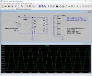
I'm trying to determine the saturation current for a SE transformer. In order to get grips on things I made the following test setup (see below noted picture).
V1=signal generator set to sine 100Hz 10Vpp
V2=lab supply 0-32V 0-5A
L1, L2, L3=primary winding (consisting of 3x in series)
L4, L5, L6, L7=secundary winding set for maximum voltage
OUT > connected to an oscilloscope
The idea here is that if I apply a signal via the coupling cap C1 the transformer will output an AC voltage relative to its pri-sec ratio. When I start applying a current through the primary winding I should hit a point where the core saturates, at this point the sine wave should see a significant distortion.
Problem is I can crank the current up to 500mA (highest I dared to go as it is >2x the rated specification) and the sine wave looks just great with no visible distortion.
What am I missing here, and more importantly, how would I tackle this another way?
Attachments
Last edited:
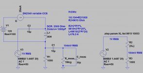
 . Also 100Hz saturation current will be < 30Hz saturation current.
A good way to measure saturation regards applying a DC voltage (pulse) and measuring the voltage over the inductor as a function of time. A simple device is described here Power inductor tester
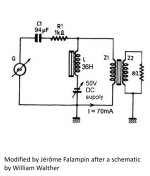
Block it with large inductor (ETF2009 OPT measuring set).The power supply doesn't know.
Attachments
Last edited:
I don't see how there's a DC current path back into the signal generator, but if you can argument how then I'd be interested to learn the mechanism behind it.
DC current won't go through a capacitor. I think what is happening is when the 100Hz signal generator drive a voltage that is lower than the DC supply. The DC supply will charge the 100uf capacitor (follow the AC generator signal). Since all this is above ground, the amp meter in the power supply will just give you the average current.
SSassen,
It appears that you are testing a high impedance Primary by driving it from a low impedance DC source and low Ohms series resistor, and perhaps a low impedance AC source. Those low impedance source(s) are swamping out the impedance of the saturated primary.
Here is another method:
First things first, be very careful of generating high voltage spikes. Do not [quickly] connect or disconnect a DC current from a transformer. Instead, connect, then bring the current up Slowly. Then when done testing, Slowly reduce the current to Zero, and only then disconnect from the transformer.
Also, to protect the amplifier, bring the current up slowly, and down slowly. Quickly connecting a large current, will cause the blocking capacitor to pass very high transient currents back to the amplifier (and may destroy it).
Method: Use a 5Hz signal from an amplifier with a series 100 Ohm power resistor; a very large capacitance blocking capacitor; and the DC power supply with a series 100 Ohm power resistor. Connect all that to the Secondary winding, in the same manner as you did on the primary winding. Now you have 50 Ohms driving a 4 Ohm, or 8 Ohm rated secondary winding.
Then use 10Hz, and repeat.
Then use 20Hz, and repeat.
Then use 30Hz, and repeat . . .
Once you have a secondary current that saturates versus the lowest frequency you will need the amp to produce, you can calculate the maximum equivalent DC primary current for that frequency signal. Of course, a larger AC signal in the actual amplifier, will saturate earlier than the lower signal amplitude you use in the test.
Square Root of (Z Primary/Z Secondary) = turns ratio Example Square Root(5k Ohm Primary/8 Secondary) = 25
Secondary saturation current / turns ratio = Primary saturation current Suppose saturation occurs at 3A on the secondary Example 3A / 25 = 0.125A DC on the primary (125mA)
When you (I was) a young electronic technician (many decades ago) in the middle of the Pacific Ocean on a US Naval Destroyer, with the Captain breathing down your neck; but you do not have proper test equipment, a wide range of available parts, etc. . . . you figure out how to test and fix an important piece of electronic equipment.
Happy testing!
Last edited:
SSassen,
Just remember, if you have a secondary that has a DCR of 0.5 Ohm, and you pass 3 Amps through it, that is 4.5Watts dissipated in the secondary wire. It can get Real Hot!
P = (I)Squared x R
DC Ams is the same as RMS Amps.
Be careful not to smoke the secondary wire. A low power output transformer will not put 3 Amps RMS continuously out to an 8 Ohm load. That would be a 3 x 3 x 8 = 72 Continuous Watts transformer.
Last edited:
Yet another method uses a bridge rectified low voltage transformer secondary to pass a DC and an AC current through the DUT transformer primary winding and then through a series connected current sense resistor. Depending on the source transformer voltage, and the sense resistance, the level of DC and AC currents can be varied to obtain test points for increasing DC current, and AC current can be made fairly low so as to determine the droop in small-signal inductance along the BH curve.
I typically use this technique for power system chokes, but the technique works equally well for SE OT's.
https://dalmura.com.au/static/Choke%20measurement.pdf
I use my vintage valve tester to provide a very convenient multiple stepped AC voltage source (with sufficient current grunt for all the chokes and OT's I've tested due to the tester supporting a wide range of valve heaters) - strangely my valve tester gets far less use for testing actual valves!
- Status
- This old topic is closed. If you want to reopen this topic, contact a moderator using the "Report Post" button.
- Home
- Amplifiers
- Tubes / Valves
- Determining SE transformer saturation current?