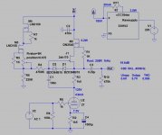
I am reviving my 27 tube preamp project that I have been putting off for some time. My original thought was to use Ale Moglia's design using his gyrator.
http://www.bartola.co.uk/valves/2016/04/23/27-preamp/
I became a little concerned with the gain when I realized that my sources had higher levels than I thought. But then I noticed Ale's design for a 26 tube preamp with an OT, which greatly reduces the gain.
http://www.bartola.co.uk/valves/dht-pre-amplifier/26-dht-pre-amplifier-gen3/
I would like to save dealing with the complexity of a DHT tube for a later project. However, given that the 27 tube is essentially an IDHT version of the 26 tube, I am beginning to think that I could use the 26 design (except for the heater supply) with the 27 tube. I would then use ac for the heaters and use Ale's suggestion to add a 1K5 resistor in the cathode with its decoupling cap, remove the battery and C1, and change R1 to 47k in the 27 design.
That leads me to my 2 questions: 1) Does anyone see a problem with my plan? and
2) I recall that Salas says to have the input voltage to his SSHV2 20 volts higher than intended output, but Ale's 26 schematic shows the SSHV2 input to be 95 volts higher. than its output. Can anyone tell me why that would be the case?
Thanks a lot for any help anyone can give me.
Sounds like you're on the right track for the audio circuit. I would make R1 larger than 47k, similar to the input on the transformer-coupled schematic (100k vol pot and 510k grid leak resistor).
Regarding #2, I'm sure Salas meant to have at least 20V headroom for the regulator. These regulators need some voltage headroom to operate and maintain a constant output. Ale's implementation has more than minimum, probably a result of the power transformer he had on hand and the target B+ more than anything.
Regarding #2, I'm sure Salas meant to have at least 20V headroom for the regulator. These regulators need some voltage headroom to operate and maintain a constant output. Ale's implementation has more than minimum, probably a result of the power transformer he had on hand and the target B+ more than anything.
I think Type 27 is a wonderful tube..
If I can ask a question; Can the gyrator load really operate with just 25 volts across it and still swing AC signal voltage?.
Actually, I think this stage needs a much higher B supply. 25 volts across the plate load, how much of that is consumed by compliance of the plate load and what is left for signal swing?
I note 2v output.
Of the available voltage between plate and B supply, how much does the gyrator consume simply to function, and what is left for signal swing?.. Or so long as voltage compliance is met, is that whole plate to B supply differential available to swing AC voltage?
Thanks.
Thank you, Sodacose. Your response is encouraging. What is the effect of raising the grid leak resistor value? I was thinking of using the MUSE IC chip for volume control. I am not sure of its output impedance, but it recommends a load of at least 47K. Would the substitution of this in place of the 100k pot pose any problems?
Hanze, your question is beyond my level at the moment. I seem to recall that one of Al's blogs mentioned clipping at 18 volts output, but I may be mistaken. (Or it may have been with respect to a different circuit!)
Hanze, your question is beyond my level at the moment. I seem to recall that one of Al's blogs mentioned clipping at 18 volts output, but I may be mistaken. (Or it may have been with respect to a different circuit!)
Hanze, your question is beyond my level at the moment. I seem to recall that one of Al's blogs mentioned clipping at 18 volts output, but I may be mistaken. (Or it may have been with respect to a different circuit!)
If the plate load does not store energy (not an inductive load), the max signal voltage will be limited by (usually, and useful enough for illustration) the amount of DC voltage across that plate load.
I'd like to ask if with 25V across the gyrator, can one expect the same max output voltage as if resistor loaded, or does the gyrator 'consume' a portion of that available DC voltage to operate?
No probs with 100k grid leak resistor BTW.
- Status
- This old topic is closed. If you want to reopen this topic, contact a moderator using the "Report Post" button.
- Home
- Amplifiers
- Tubes / Valves
- 26 schematic for 27 tube preamp