I use UF5408 all the time... They are perfectly fine.
I'd probably use these if I wanted Schottky... STPSC2H12D STMicroelectronics | Discrete Semiconductor Products | DigiKey
I'd probably use these if I wanted Schottky... STPSC2H12D STMicroelectronics | Discrete Semiconductor Products | DigiKey
That's good to know haha. I have a bunch of UF5408 although I typically use 35A bridge rectifier as I've yet to destroy one
I've cracked one in half with a short LOL
Your tag line is great BTW. I've connected a 10,000uF 150V cap backwards... A 5W 47R resistor got orange hot before the power was cut. It still works and so does the cap! "They don't make'em like they used to, eh?"
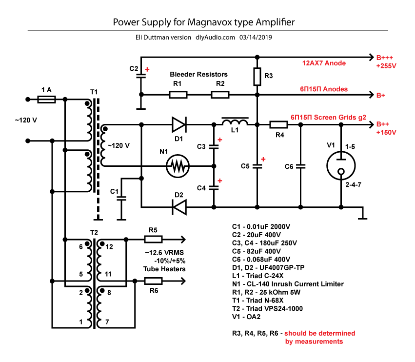
Your schematic is wrong for R5 and R6. They should be 100 ohm and tie togethor to form an artificial center tap in the middle. This centre tap then goes to earth (or in the case of the schematic you linked to, to one of the output valve cathodes which will be at some positive voltage). The two transformer wires go straight to the heaters set up for 12V as you showed in one of your previous schematics.
The B++ is the screen voltage. I haven't read the rest of this thread, but if someone recommended 150V then should probably stick with that. 255V will allow more power but will probably need a different load impedance.
The B++ is the screen voltage. I haven't read the rest of this thread, but if someone recommended 150V then should probably stick with that. 255V will allow more power but will probably need a different load impedance.
I don't agree.Your schematic is wrong for R5 and R6. They should be 100 ohm and tie togethor to form an artificial center tap in the middle. This centre tap then goes to earth (or in the case of the schematic you linked to, to one of the output valve cathodes which will be at some positive voltage). The two transformer wires go straight to the heaters set up for 12V as you showed in one of your previous schematics.
I think the idea as drawn on the schematic above, is to choose the value for R5/R6 to make sure that the heater voltage is correct (12.6 V RMS -10% / +5%). If the AC line voltage and the chosen transformer are working together to provide the correct voltage, R5/R6 can be omitted.
The 'artificial center tap' is a separate issue, and I agree it's useful and should use 100 or 200 ohm resistors.
Some of the resistor values cannot be calculated easily (or accurately) from simulations in my experience and as the schematic indicates, should be found by experiment.
rpl was referring to another schematic linked to in his post #178 (where the 100 ohm resistors were used for a centre tap) then confusing them for the differently located resistors in his schematic. So I guess I chose my words badly when I said his schematic was wrong  . As you say he may or may not need resistors in both locations. If needed for voltage drop to get down to 12.6V they will likely be under 1 ohm with a rating of a few watts.
. As you say he may or may not need resistors in both locations. If needed for voltage drop to get down to 12.6V they will likely be under 1 ohm with a rating of a few watts.Got any recommendations for a general purpose Schottky that can be used? Might fix a hum issue I have related to transformer secondary ringing.
Depending on how much stress the diodes are subjected to, either this 600 PIV part or this 1200 PIV part should get the job done.
Sorry no insulated 1200 PIV part. Maybe Cree will do that, in the future.
I've cracked one in half with a short LOL
Your tag line is great BTW. I've connected a 10,000uF 150V cap backwards... A 5W 47R resistor got orange hot before the power was cut. It still works and so does the cap! "They don't make'em like they used to, eh?"
Lol yes the day I changed the signature line, I did exactly that.
A resistor got hot, but it was the bright glow of the tube that alerted me to danger! It all still works, but the heat was enough to buckle the cathode and leave a bit spot mark.
Actually, yesterday I learned why you don't exceed the cathode heater voltage as cathode follower! Started up with signal applied by mistake and the tube runaway quicker than the bias could stabilise it again. Drop the B+ just enough and all is still good.
(If this were silicon, I'd have released the magic smoke from several Bits by now!)
Funny, I've never elevated the heater, and I've never had a problem. I routinely run up to 165V cathodes on Soviet tubes like 6N*P... The heaters all run 12VDC, 2 tubes in series, sets of 2 in parallel.
I Have had KT88 and KT120 tubes arc though. Running 560V B+ in triode connection.
I Have had KT88 and KT120 tubes arc though. Running 560V B+ in triode connection.
I measured the output voltage from the Triad VPS24-1000. It's 14.64V without any load.
14.64V - 12.6V = 2.04V
2.04V / 0.91A = 2.24 Ohm
2.04V * 0.91A = 1.85W
Is it correct that for R5, R6 I will need 2.2 Ohm 2W resistors like this one:
FMP200JR-52-2R2 Yageo | Mouser
Or should it be 1.1 Ohm as we have two resistors in the line?
14.64V - 12.6V = 2.04V
2.04V / 0.91A = 2.24 Ohm
2.04V * 0.91A = 1.85W
Is it correct that for R5, R6 I will need 2.2 Ohm 2W resistors like this one:
FMP200JR-52-2R2 Yageo | Mouser
Or should it be 1.1 Ohm as we have two resistors in the line?
Last edited:
I'd try it with a load before committing to values for adjusting resistors.I measured the output voltage from the Triad VPS24-1000. It's 14.64V without any load.
Can you quick wire some sockets and with old/'tester' tubes to see if the voltage drops?
As you can see, I'm a wire it and test it' guy, not a 'sim' person!
Member
Joined 2009
Paid Member
maybe try a Silicon Carbide rectifier - no minority charge carriers means switching noise even less. e.g. C4D02120A. I would still consider snubber them (or perhaps more accurately, the secondary of the power transformer which will have leakage inductance waiting for a 'kick').1N4007s in the simulations OK, but UF4007s or (even better) Schottkys in the build. The difference in the amount of switching noise generated is huge.
Last edited:
...Can you quick wire some sockets and with old/'tester' tubes to see if the voltage drops?...
This is my very first tube amp project. I don't have any old/tester tubes yet
Is it valid to assume that if the heater current for 6BQ5 is 0.76A and voltage 6.3V
then its heater resistance is 6.3/0.76=8.2Ohm. I don't have spare tubes but I could
probably find 8 Ohm 6.3*0.76=4.8W (~5W) resistor. Will it simulate the tube's heater?
"Try it and see" is usually best for this sort of thing but the maths would be:
14.64V unloaded
12V loaded with 2A (assuming datasheet is correct)
Transformer internal resistance (14.64-12)/2 = 1.32 ohms
Voltage drop required under 0.91A load = 14.64-12.6 = 2.04V
Total resistance required = 2.04/0.91 =2.24 ohms (your calc)
Extra resistance required = 2.24-1.32 = 0.92 ohms or ~ 2 x 0.47 ohms each dissipating about 0.4W (0.91^2 x 0.47). So use at least 1W resistors so they don't get too hot.
Or alternatively just use one 12V winding instead of paralleling them, then the voltage will probably be about right (a bit low but OK) without any resistors.
RPI,
in Post # 188, you said: "Is it OK to switch this power supply on without any load?"
At first I mistakenly took that to be a B+ supply, but most of what I am about to say also applies to DC filament supplies, fixed bias supplies, and negative supplies for long tail CCS.
“What can happen if I run my B+ without a load”? This applies to many vacuum tube amp power supply designs.
Answer number 1, you could get shocked, even though the amp is off! Suppose you did not have Bleeder Resistor(s) in your B+ circuit. You turn the amp on, then turn the amp off. You go get a cup of coffee and come back. You get your hands in the amplifier and find out there is still B+ voltage there. “I’m shocked” you say. Safety first, use a bleeder resistor.
Answer number 2, you might exceed the voltage ratings of the electrolytics, and of the rectifier diodes. Suppose the secondary is rated for 350V-0-350V under 200mA load, full wave rectification. Suppose the electrolytic caps are rated for 500VDC. Suppose the diodes are rated for 1000V Peak Inverse Volts (PIV).
Under load, you have 350V x 1.414 = 495V on the electrolytic (close to their 500V rating).
Under load, you have -495V peak at one diode anode, and +495VDC at the same diode cathode. The differential voltage across that diode is - 495V - (+495V) = 990V Peak Inverse Voltage (close to the 1000V diode PIV rating).
As you can see, this example I picked (on purpose), the B+ circuit is already very near the maximum voltage ratings of the electrolytics and diodes.
But . . . The 350V-0-350V secondary is not under load. Suppose the DCR of one 350V secondary is 200 Ohms. We had 0.2A x 200 Ohms = 40V when there is a 200mA load. That means the transformer open circuit secondary voltage is actually 350+40V-0-350+40V = 390-0-390V. So the unloaded B+ is 390 x 1.414 = 552V peak (way over the electrolytic 500V rating). And the diode sees -552V peak at the anode, and +552VDC at the cathode = 1104V (way over the diode 1000V PIV rating).
Answer number 3, there is a good reason to use parts with ratings that have a little margin, so we design reliability in. Now what else can require that? When the tubes are warming up, there is no B+ load (consider that when you choose part voltage ratings). When the transformer primary is rated for 120V, but you have 128V like at my friend’s house, consider that: 128/120 = 1.067 times; 350 x 1.067 = 373V. What . . . that 350-0-350V B+ secondary is putting out 373-0-373V, or 527V peak (even under load). . . surprise!.
One more thing about not loading the power transformer. When you turn on the transformer, and than turn off the transformer, there is an inductive kick. Sometimes that can destroy one or both B+ diodes because their PIV rating is exceeded. (that happened to me once, so I try and avoid repeating it). I use higher PIV rated diodes, or I start with the tube filaments loading the transformer when I am testing unloaded B+. The filament load helps to reduce the inductive kick. In some cases I used diodes that are rated for higher PIV, but are also rated for higher forward amps (which means the PIV is across a larger area silicon chip).
I hope these comments are helpful.
I found in my garbage powerful resistors which I used to simulate speakers long time ago. I connected 8Ohm resistor to the transformer to check its output voltage under load.
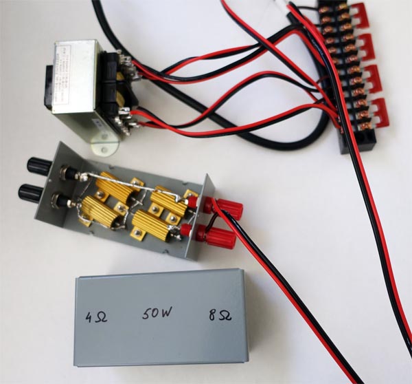
It was 13.2V. So it's in the desired range 13.23V-11.34V. More likely there is no need in R5, R6. But I'll order 0.47Ohm resistors just in case. I need to order bleeder resistors anyway.
I'm trying to define the values for R3, R4 now. According to the reference schematic B+ = 265V, B+++ = 255V, hence the drop on R3 is 10V. From the 12AX7 datasheet the anode current is 1mA. That gives 10V/0.001A=10kOhm for R3.
The drop on R4 is 265V - 150V = 115V. The current is 4.5mA for 6BQ5 for B++. That gives 115V / 0.0045A = 25kOhm for R4.
Is it correct calculation? I attached PS schematic again for easier reference:
Other than the danger of electrical shock are there any other issues to switch the power supply on without load? Is it possible to tune it - set all required voltages without load? Is it OK to keep OA2 unloaded? I was going to complete PS first and then switch to the amp itself.
- Status
- This old topic is closed. If you want to reopen this topic, contact a moderator using the "Report Post" button.
- Home
- Amplifiers
- Tubes / Valves
- Need 3-5W tube amp