This is interesting.
Since his design uses two transformers in parallel, I wonder if it would make more sense to connect them in series instead. It would certainly allow for a lot more headroom at low frequency, and I can't see much in the way of a down side. The ratio could be preserved by connection the secondaries in series too. This would give an allowable primary voltage of 480V at 50Hz before core saturation, and 240V at 25Hz, which is way more headroom than the previous 120V at 25Hz.
OK. So I built it up with the transformers in series. So far so excellent.
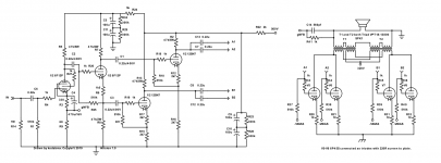
Here's the VA/PI as built.
EDIT: And the output stage.
Now I'm modifying the other monobloc. In a couple of hours, I should be able to hear them
Attachments

Last edited:
I mislabelled the phases, oops.
Also I forgot the gNFB values.
I also swapped the FR607 diodes i was using for the DC heater supply for these: STPS60L30CW STMicroelectronics | Discrete Semiconductor Products | DigiKey
And now I have 12V instead of 11.4V for the heaters!
Also I forgot the gNFB values.
I also swapped the FR607 diodes i was using for the DC heater supply for these: STPS60L30CW STMicroelectronics | Discrete Semiconductor Products | DigiKey
And now I have 12V instead of 11.4V for the heaters!
Attachments
I really don't want to sift thru the stack to figure out what V5,6,7,8 are. Hints?
If I “get it” though, the dual-series-parallel approach with the transformers keeps them each near flux-neutral during quiescence. And slews them in exactly the same way during both positive and negative signal excursions. And puts the secondaries in series, potentially driving the speakers with 2× the volts, but then that'd be 4× the power. But wait… there aren't 4× the number of output valves. Well … 4 of them.
The mind boggles.
Just saying,
GoatGuy ✓
I really don't want to sift thru the stack to figure out what V5,6,7,8 are. Hints?
If I “get it” though, the dual-series-parallel approach with the transformers keeps them each near flux-neutral during quiescence. And slews them in exactly the same way during both positive and negative signal excursions. And puts the secondaries in series, potentially driving the speakers with 2× the volts, but then that'd be 4× the power. But wait… there aren't 4× the number of output valves. Well … 4 of them.
The mind boggles.
Just saying,
GoatGuy ✓
The primaries are in series and secondaries are now in series, versus their previous respective parallel connections.
The ratio of the combined transformer is the same, but now there are more turns per volt, which means the transformer now has a slightly bigger series impedance, but should be able to push four times more power at low frequencies intk a given impedance load before the core saturates.
I built the other one and tested them.
26V RMS 1kHz = 112W into 6R
26V RMS 30Hz = 112W into 6R
19V RMS 20Hz = 60W into 6R
Not too shabby!
Thanks to Max for the series idea!
No problem, happy to help!
Do you have data on the previous connection?
Not really, the VA/PI would clip before the output, but I'm sure 30Hz wouldn't have been cleen at full power in parallel mode!
The 6R load reflects as 1k plate to plate.
(((460/36)^2)*6) = 979
Now all you need is an input filter which has a -3dB point of 20Hz, to make it impossible to drive the amp into clipping at 20Hz before it clips in the mid band.
I guess I could... The tubes pass lower frequencies than my Yorkville AP1200 amp... I could make it switchable and call it a rumble filter but I'm probably too lazy.
So there you have it, a pretty kick *** 100W triode amp for under 1000 CAD")
No sense in solving a problem which isn't actually a problem! Nice amp, btw.
I'm running Russian tubes too, 6R3S.
This is interesting.
Since his design uses two transformers in parallel, I wonder if it would make more sense to connect them in series instead. It would certainly allow for a lot more headroom at low frequency, and I can't see much in the way of a down side. The ratio could be preserved by connection the secondaries in series too. This would give an allowable primary voltage of 480V at 50Hz before core saturation, and 240V at 25Hz, which is way more headroom than the previous 120V at 25Hz.
Thanks again, Maxhifi. This scheme truly works well.
I'll ask you this though. The coils need to be derated? If the coils are both 250VA one school of though might say sum them because there is twice the core area making a 500VA overall solution, but I'm inclined to say the added core size is needed to support 25Hz so the two combined are only worth 250VA@25Hz or 500VA@50Hz??
Last edited:
I've seen those 6R3S but never had any to use. Tetrode connected?
Cheapified "Civil" re-mix of 829.
Thanks again, Maxhifi. This scheme truly works well.
I'll ask you this though. The coils need to be derated? If the coils are both 250VA one school of though might say sum them because there is twice the core area making a 500VA overall solution, but I'm inclined to say the added core size is needed to support 25Hz so the two combined are only worth 250VA@25Hz or 500VA@50Hz??
The primary coil of one transformer is rated at 240V, 50Hz. If you want to use it at 25Hz, you must reduce the voltage to 120V, to avoid core saturation. You also should keep the current through the primary at the same level in either situation. This means that you are correct, the maximum power of the transformer at 25Hz is half what it is at 50Hz.
Using two transformers doubles the power of one - for example if one transformer was rated 500va at 50Hz, it is good for 250va at 25hz, and two together are good for 500va at 25hz.
What I think you are missing though, is impedance. To load the tubes properly, you need to present them with a fairly high plate to plate impedance. Because of this, you come nowhere near the maximum current capability of the transformer, and therefore the actual power output is reduced even farther, because the situation it is used in cannot take proper advantage of the transformer's current rating. This is probably a good thing though, since it keeps loss and distortion down.
Your amplifier is very powerful for a tube amp - I think at this point, best thing to do is just enjoy it! Either that or begin design work on a preamplifier.
Last edited:
Cheapified "Civil" re-mix of 829.
They really pack a lot into a small envelope... not the world's most reliable tubes! I wish I could find a better quality equivalent.
A 500VA transformer at 240V has current rating of about
2A RMS, so to get 500VA out of it, you need a primary impedance of about 250 ohms. The most power you can get out of it at 1000 ohms, is about 58W, assuming the core saturates at exactly 240V at 25Hz. In reality it will be a little higher, and more or less reflects your empirical results.
2A RMS, so to get 500VA out of it, you need a primary impedance of about 250 ohms. The most power you can get out of it at 1000 ohms, is about 58W, assuming the core saturates at exactly 240V at 25Hz. In reality it will be a little higher, and more or less reflects your empirical results.
Well using two 250VA coils, I get 112W at 30Hz or 1kHz... I only get about 60W at 20Hz though.
Also, they can handle more than 240V, and they deal with a DC misbalance easily. I just replaced a blown cathode resistor that had sublimed but unless I cranked the volume, I didn't notice, There was a 100mA misbalance, but the transformer didn't seem to care very much.
(((240÷18)^2)×6)=1066Ra-a:6R
Also, they can handle more than 240V, and they deal with a DC misbalance easily. I just replaced a blown cathode resistor that had sublimed but unless I cranked the volume, I didn't notice, There was a 100mA misbalance, but the transformer didn't seem to care very much.
(((240÷18)^2)×6)=1066Ra-a:6R
Last edited:
Well using two 250VA coils, I get 112W at 30Hz or 1kHz... I only get about 60W at 20Hz though.
Also, they can handle more than 240V, and they deal with a DC misbalance easily. I just replaced a blown cathode resistor that had sublimed but unless I cranked the volume, I didn't notice, There was a 100mA misbalance, but the transformer didn't seem to care very much.
(((240÷18)^2)×6)=1066Ra-a:6R
Sounds like those transformers have some headroom built into them - very nice performance, I imagine you are never wanting for power!
- Status
- This old topic is closed. If you want to reopen this topic, contact a moderator using the "Report Post" button.
- Home
- Amplifiers
- Tubes / Valves
- 6P45S PPP Monoblocks.