Do you NEED a screen resistor?
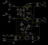
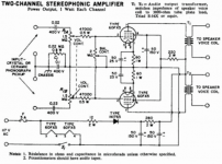
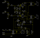
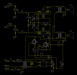
I've got an amp on the table. A 60FX5 stereo amplifier, schematic attached. I can't find a definitive answer as to whether or not I must supply a screen resistor or if my 115V regulated supply is OK.
I've measured screen current at 12mA on one tube and 10mA on the other(not very matched set, cathode current is 53/45mA). The hot tube runs 1.38W of screen power which is well under the 2W maximum. Datasheet says 115V for screen and 110V for plate so that's what I'm running but I omitted the 220ohm resistor that is in the RCA schematic on the screens.
I had originally built this thing exactly like the RCA schematic, however, a bad socket contact left the left tube, which is now the hot one, with a floating grid that was causing the tube to draw current like a madman and it promptly smoked the 280ohm filter resistor. I thought it was a sign that I needed to just do a regulated B+ so I swapped a burnt carbon comp resistor for a solid state setup. I measured peak cathode voltages of 33V during troubleshooting after the regulator install which puts the runaway tube at 550mA of current draw, might have to play with A2 and a jfet input!
Gotta track a bit of hum, I think it's a miscalculation of the overhead my isolation transformer offers for B+. 50uF was chosen to reduce the load on the IRF610 MOSFET and reduce peak rectifier loads over 100uF but requires it to swing a lot more. I think it might dip under regulation minimum. Could be the 60V heaters but I doubt it as this compact amp has maybe 3 inches of ac wire that is plenty away from the input. Could also be the 47K grid stoppers that go over my output transformers too but since it's a line-input level I doubt it a bit too.
Amp will be updated with a fat 10mm red power led on top fed with a B+ CCS and tube guards once I get the damned thing working like I want it to.
Hum aside, it sounds great playing into some 4 ohm speakers and using my cell phone as a source. I'm surprised that it doesn't lack the bottom-end like I sort of expected with the small transformers. At about a watt of output it isn't going to shake any windows but it does sound very good for what it is. Interesting note, once the tubes are hot I've been able to leave them off for up to a minute and get some sound immediately upon firing the amp back up.
Attachments
Last edited:
I like to use a single shared screen resistor between two tubes in an output pair, even with a regulated supply. a single ~100R for the two should do fine, or something like 150~220R each. Without a screen resistor I've gotten stability issues on some builds, and the resistor being installed fixed it (oscillation types of things) without modifying anything else.
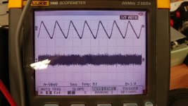
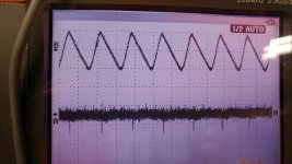
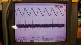
I knew it didn't sound like typical supply hum. Trace A is B+ after the regulator, grid, and speaker output, in that order. Trace B is the supply cap right after the rectifier. It does look like the pulse happens at 120Hz at the rectification peaks.
My portable scope from work is noisy and almost worthless at the 50mV setting but I'm able to see the output 'hum'. Looks like it gets into the grid circuit and I'm able to make a channel silent by cranking balance to a channel completely which grounds the opposing grid. The grid circuit is pretty high-impedance so I think coax from the balance pot might fix it by itself.
My portable scope from work is noisy and almost worthless at the 50mV setting but I'm able to see the output 'hum'. Looks like it gets into the grid circuit and I'm able to make a channel silent by cranking balance to a channel completely which grounds the opposing grid. The grid circuit is pretty high-impedance so I think coax from the balance pot might fix it by itself.
Attachments
Last edited:
FYI, this is not a line-powered amp and it does use a power transformer. I only included the RCA line powered schematic as a reference. The black schematic is what I built off of. I did end up adding a ground breaker switch but that is the only deviation.
I'll install the 'stock' 240 ohm for the screens tomorrow when I'm messing with this guy again and installing some tiny coax.
Also, turns out the socket WASN'T the cause of my 'hot' tube taking current like crazy, that tube is actually bad. Must have an intermittent short or something that only occurs when the tube is fired up cold but doesn't show until after the heater gets hot. Replaced that bad boy and it seems to operate normally and WAY closer as cathode bias is now 2.5V and 2.7V and current draw is right on the money at 0.24A.
I'm a dumbass.
I ran coax for all of my internal connections to the grid and while it made a little difference it wasn't much... In my haste to build this guy I completely neglected the fact that the RCA schematic is based on line-input and my circuit uses a transformer. My buzzing was from rectifier oscillation and while B+ is regulated and clean I have a long 60V antenna directly coupled to the ringing transformer within the tubes themselves. Added snubbers to the diode bridge and across the transformer secondary and it's as quiet as can be.
I ran coax for all of my internal connections to the grid and while it made a little difference it wasn't much... In my haste to build this guy I completely neglected the fact that the RCA schematic is based on line-input and my circuit uses a transformer. My buzzing was from rectifier oscillation and while B+ is regulated and clean I have a long 60V antenna directly coupled to the ringing transformer within the tubes themselves. Added snubbers to the diode bridge and across the transformer secondary and it's as quiet as can be.
")
- Status
- This old topic is closed. If you want to reopen this topic, contact a moderator using the "Report Post" button.
- Home
- Amplifiers
- Tubes / Valves
- 60FX5 Amplifier Build