Watts out would require some real world measurements, but I did run them up to 185mA with 250V on the plate without any problem.
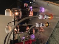
I don't need all that power though so biased lower for perhaps longer valve/tube life. These Lundahl transformers are kind of big and I wanted to do something nice with them...
I don't need all that power though so biased lower for perhaps longer valve/tube life. These Lundahl transformers are kind of big and I wanted to do something nice with them...
Last edited:
Today I got an opportunity to finish up my single 6DN6 amp using 10W Edcor GXSE 10W 5K outputs. I got roughly 8.5W clean sines across the majority of the audio bandwidth and I suspect a lot of the rolloff was due to the output being at the upper end of its power capabilities. I have 400v B+, 146V on the screens and biased at 52mA using a LM317 as a current sink. Looks pretty decent with just a touch of global feedback.
Assuming this is somewhat optimal as far as loading, if he happy with 20W from three in PSE. One thing the Golden Tube outputs has that the Edcor don’t is a cathode feedback winding that I can use as additional feedback if necessary.
Assuming this is somewhat optimal as far as loading, if he happy with 20W from three in PSE. One thing the Golden Tube outputs has that the Edcor don’t is a cathode feedback winding that I can use as additional feedback if necessary.
Attachments
Last edited:
decide67,
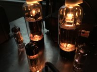
That is a great picture of a good looking amplifier.
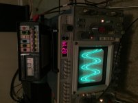
That is also a nice analog Tektronix scope.
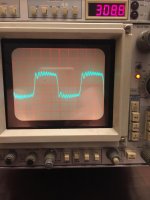
What is the ringing frequency in your post # 42?
(1/time from peak to peak of the high frequency)
Are you using Schade feedback?
Are you using global feedback from the transformer secondary?
Are you using both feedback modes?
You are using Beam Power mode, right?
I am considering for the first time to do either a Pentode or Beam Power mode amp of my own design.
I have always done either DHT, or Pentodes and Beam Power tubes in Triode Wired Modes.
That is a great picture of a good looking amplifier.
That is also a nice analog Tektronix scope.
What is the ringing frequency in your post # 42?
(1/time from peak to peak of the high frequency)
Are you using Schade feedback?
Are you using global feedback from the transformer secondary?
Are you using both feedback modes?
You are using Beam Power mode, right?
I am considering for the first time to do either a Pentode or Beam Power mode amp of my own design.
I have always done either DHT, or Pentodes and Beam Power tubes in Triode Wired Modes.
Last edited:
Are you using Schade feedback?
Are you using global feedback from the transformer secondary?
Are you using both feedback modes?
Thanks! As Wavebourne pointed out, it’s the source ringing in the photo. This is just global feedback running purely Pentode operation. I may consider some Schade feedback. Global seems to cut the “edge” off, but presents overshoot that may also be an issue with the dinky Edcor outputs.
It’s all in good fun, so I’m going to tinker with it some more and then I’m just going to start drilling for the SE-40 retrofit.
")
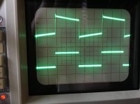
Here is open loop 1kHz from my scopes reference square.
Attachments
The GT SE outputs have a separate winding for cathode feedback. Should I use this, or just rely on the Schade feedback for lowering output impedance and increasing stability?
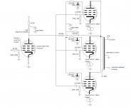
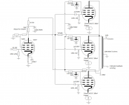
Also, I’ve never used a Pentode in Pentode as a driver. Do I just attach the grid to the driver supply via a resistor or pi filter? Here is a proposed starting schematic. I know there are better screen regulators, but I like gas tubes, so I’d like to use them.
Thanks!
Also, I’ve never used a Pentode in Pentode as a driver. Do I just attach the grid to the driver supply via a resistor or pi filter? Here is a proposed starting schematic. I know there are better screen regulators, but I like gas tubes, so I’d like to use them.
Thanks!
Attachments
Oh oh oh that YL1350 miracle tube!The Pa of sweep tubes is rather low, you have to put minimum two or three in parallel.
This one can do it on it's one !
Mona
I suggest you'd better keep your hands off them, 'cause there were produced less than a thousand items. I know it from a former employee at the TELEFUNKEN Ulm plant who showed me the production lists he had salvaged. How many might have survived 'till today?
Best regards!
I see one issue with the schematic as drawn. You show the 5.6K resistor that feeds the output tube screens connected to the output tube's plate. This will burn a large portion of your output power and make the 100 uF cap unhappy. I assume that you really have it connected to B+. If not, you should.
The "experts" opinion for "Schade" feedback is that it "doesn't work with a triode driver." This is because the Rp of a triode varies with signal, and the feedback amount is dependent on three resistances. The driver's Rp, the driver's plate load, and the input resistor to the output stage. All of these are effectively in parallel and together with the Schade feedback resistor, determine the amount of feedback. I have found that Schade works well with some triodes, and totally sucks with others.
It is likely that a single triode driver will fall short on gain when attempting to drive sweep tubes to full output with some feedback applied. The 5842 in the TSE can just drive a 300B to clipping with a CD player source, and requires CCS loading to get that gain. No feedback is used.
I would start with a pentode wired driver. I am using a 6EJ7 and I use a resistive voltage divider for the screen. I feed the divider with the screen supply for the output tubes and adjust the values for about 80 to 100 volts on the input tube screen grid. You will need a bypass capacitor on the screen grid, and may want one on the cathode as well.
The current through the pentode, it's Gm, and the effective plate load resistance will determine it's gain. The plate load resistor and the "Schade" resistor are two "knobs" that you can turn, and so is the tube's plate current (screen voltage and cathode resistor affect the current).
With a 450 volt supply the input tube's plate voltage should probably be kept somewhere in the 150 to 300 volt range. I'm using 200 volts as a target.
More tube current will increase the gain, but it pulls down the plate voltage. Lowering the plate load will bring the voltage up, but also reduces the gain. There are a lot of knobs to turn and ALL of them interact. Each will affect the sound of the amp in some way. Keep the input tube's plate voltage well over 100 volts to avoid distortion on music peaks.
I start an exercise like this in LT Spice. I use the 6EJ7 model since it seems to be relatively good. I will then breadboard the amp, stick in a 6EJ7 and make it work. Then I'll put in whatever driver tube I want to use and tweak on the parts until I get the gain, power and distortion that I want. There are several tubes that are pin compatible with the 6EJ7 that have more Gm and some are on the dollar list, while others like the 12BY7 are expensive. I go for the $1 tubes.
I have just started on the hardware proto phase. So far my SE amp design exists only in the mind of the simulator. My goal is to see how much power I can get through a set of Hammond 1628SEA OPT's that I have had for 12 years. I may use several 25DN6's since I have them, or I may use something bigger to reduce the tube count.
Do you really want 6 X 0A3's in your amp. if you do, that's OK, but if you don't just use one with a mosfet butter and feed all 8 tubes with one 0A3 tube. That's what I am doing......I will probably ditch that tube for a 150 volt zener, because I don't like making holes in metal chassis.
CFB works wonders with some OPT / speaker combinations, and doesn't do much for others. The only way to tell is to try it. Other than the gain reduction, it doesn't affect the Schade feedback, so get the amp working without CFB, then add it and test. I find that it helps the bass a lot on cheap OPT's since it improves the damping factor.
GTA SE-40 Transformers
I have the regular and special edition version of these amps. The transformers are very good.
sacthailand tested them and published their results. If you haven't already viewed this it is worth a look.
Goto SACThailand
Select the Transformers tab on the left
click on Silk output testing under the first silk output transformer.
scroll down to the Golden Tube SE-40 transformer and you will see screen caps of the square wave response.
click on See Graph Click Here and you will see the frequency response.
-1db at 25 hz and 65khz
Steve
Hey TubeLab,
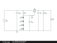
As always, thanks for the detailed explanation! Here is a revised copy on the schematic. I looked at the 6AG7 because it has a high transconductance of 11000. I haven’t filled in many values around it for the resistors but testing will yield that. I pulled the driver supply from the B+, but I suppose I could use a Zener string or another gas tube or two to feed it with a regulated supply. Thoughts?
As for the 0A3 on each tube, I don’t mind the extra holes. I just figured it would look cool fired up. I could change it, but I prefer the tubes if it will work well.
Thanks again!
Attachments
What about something like the 6J11 as a driver? Transconductance of 1300 and a single compaction socket.
https://frank.pocnet.net/sheets/201/6/6J11.pdf
Or, the 6BN11
https://frank.pocnet.net/sheets/123/6/6BN11.pdf
Looks more common.
https://frank.pocnet.net/sheets/201/6/6J11.pdf
Or, the 6BN11
https://frank.pocnet.net/sheets/123/6/6BN11.pdf
Looks more common.
Last edited:
Using a 6829 as a driver with 150V on the screens and 400v on the plates, I got roughly 8.5W into a 10ohm dummy load on my 8 ohm tap of my 5K output transformer. I got over 10W into my active speakers with a 1KHz sine wave. Tubes are biased at 50mA.
Attachments
- Status
- This old topic is closed. If you want to reopen this topic, contact a moderator using the "Report Post" button.
- Home
- Amplifiers
- Tubes / Valves
- Gutted Golden Tube SE-40 (looking for suggestions)