I purchased one of those cheap Chinese tube amp kits. I did some due diligence (ie google) but not much came up. So, I figured I would give it a whirl for $140 with free shipping.
I have very little knowledge about circuits and what the various parts do. I learned which end of a soldering iron to hold just a few months ago and managed to put together the crossovers in the Parts Express Overnight Sensations
I purchased this one: 6N1+6P3P Amplifier HiFi Class A Tube Audio Vacuum Power Amp DIY Single Ended Kit | eBay
I was expecting step by step instructions but what I got is one piece of paper with a schematic and some text. In Chinese. Instead of packing it backup and sending it back I made the second mistake of going ahead and trying to build the thing. After all it is only $140. My new mantra.
The endless research done to figure out were to start led me here where I found out
A. I should have never purchased this amp because it does not come with instructions.
B. It is a poorly designed amp.
I assembled everything easily, did a quick tutorial on reading schematic and researched output transformers. The output transformers seemed easy enough so researched power transformers a little more daunting but in the end not too bad.
But, to me those where the easy parts. Everything in between looks much more difficult and the chances of me not making a mistake somewhere is slim to none. That is if I not already have not made a mistake. So, after all my long windedness. My question is what should I do next? (It is a multiple-choice question)
A. Stop wasting my time throw the whole thing away and keep telling my self it was only $140
B. Finish it, plug it in, turn it on and take out the power grid for miles then throw it away and tell myself it was only $140
C. Finish it take it to a tech before I plug it in let him/her look over it. Thus, this project will now be over $200+ for a poorly designed amp.
D. Stop now take it to a tech and let them finish it. Making this a $300+ poorly designed amp
E. None of the above.
If I'm not mistaken Wavebourne picked up one of these a while back, hopefully he chimes in soon. He built it up as a testbed for something else though. Here's a build based on one, has a schematic shown too- Tube amplifier kit from ebay
It has a few underside shots too, if that helps. How far have you gotten in the build? If you post up some pictures of the current state of things folks will be happy to help as best they can.
It has a few underside shots too, if that helps. How far have you gotten in the build? If you post up some pictures of the current state of things folks will be happy to help as best they can.
That schematic Lingwendil linked is interesting. It says 6P3P or EL34. However, the 6P3P datasheet seems to suggest that the type is electrically closer to a 6BQ5/EL84 than it is to an EL34. I don't read Hanji and could easily be misinterpreting things. That 5.4 W. is what caught my eye.
That's not a terribly bad design and can (within the limits of the provided magnetics) be made into a pretty good design. IMO, the fact that it's a point to point (P2P) setup, not a printed circuit board (PCB), works to our collective advantage.
The 5Z4P rectifier is, basically, a 5Y3 with a cathode sleeve.
If the OP is interested, I can provide a few ideas about squeezing every last drop out of the magnetics.
Attachments
Think of it like this, You are buying a pair of output transformers for $60, a power trans for $20, a choke for $10, 4 octal sockets for $10, a preamp and a rectifier tubes for $5 each plus a chassis (no paint) for $10 and the shipping cost is $18. The rest of the stuff are free. It is not a bad deal unless you already have plan to spend 2X more money.
I would also suggest using the schematic in post #2.
I would also suggest using the schematic in post #2.
Option F:
Buy Morgan Jones book on building tube amplifiers. As mentioned before the limiting factor is the magnetics, but even still one can put together a pretty decent amp with those parts.
The people here will be a huge resource, as is the book I mentioned above. Also, there are a few YouTube channels with very good video series on this subject. Blueglow Electronics and Xraytonyb both have series that are geared towards someone building their first amp.
Thanks all. But I’m a stone-cold beginner and need an entire schematic to slowly digest. I do have wavebourne’s schematic and picture down loaded from my original research I will look at it. I have watched several hours of those Blueglow videos. Very helpful and got me started. I will check out Xraytonyb and the book. A win for me right now is something that will make sound not smoke in the end.
I would also suggest using the schematic in post #2.
I "lifted" that schematic and brought it here.
I'd keep going if it were me. You have all the parts necessary and there are plenty of resources available here to help you get through the build.
It doesn't necessarily matter that the design might not be the best - it was $140 after all - but when it is up and running you'll get the sweet satisfaction of bringing an amp to life. Think of the $140 as a learning opportunity.
The schematic is the roadmap. All you need to do is be methodical when wiring and have a read of some of the 'tube amp wiring guides' available on the internet and you'll be alright!
I was researching just what the 6n1 tube was for. I guess Allensoncanon answered that. Basically, this is not a power amp with a volume but an integrated amp. I have a preamp in the same case as this amp that I was going to use with it but if I’m going to use only one source I guess there in no need. The wife asked me what I was going to use this amp for and I told her I don’t know. She has been inching to build a pair of single driver folded speakers and likes the look of this amp for the living room. I really don’t want speakers in the living room but I told her if this amp works it would make a good combo. Maybe paired with a Blusound streamer.
Also by better performance do you mean more power, less noise, more linear or more pleasant sound? Or all of the above.
Also by better performance do you mean more power, less noise, more linear or more pleasant sound? Or all of the above.
Also by better performance do you mean more power, less noise, more linear or more pleasant sound?
Technical details, if you will.
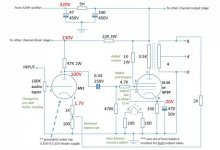
The amp employs a full pentode mode O/P tube, along with a global negative feedback (GNFB) loop. The NFB loop improves damping factor and lowers distortion. However, reducing open loop distortion, before NFB is applied, is important. The lowest open loop distortion for full pentode mode is realized by regulating screen grid (g2) B+ at a fraction of anode (plate) B+. In particular, highly irritating intermodulation distortion (IMD) is reduced. For this situation, a Zener diode stack plus the requisite passive parts should be good enough in regulating g2 B+.
In what I think was "penny pinching", a cap. (say 15 μF./400 WVDC) was left out from the 230 V. point to ground. That cap. decouples the voltage amplifier triodes from the O/P tubes and improves stability.
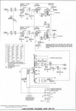
Just so it can be seen that the Chinese circuitry is not complete garbage, compare it to the provided Magnavox console amp schematic. Similarities abound.
") AAMOF, I can easily see following, for the most part, Magnavox and not the seller.
AAMOF, I can easily see following, for the most part, Magnavox and not the seller.Attachments
Apparently, I was dead wrong about the Chinese 6P3P. According to this, the Chinese 6P3P is equivalent to the 6L6G. There is incomplete congruence between the 2 data sheets. Still, I think some real progress can now be made.
40% efficiency for a 19 W. plate dissipation multi-grid O/P tube leaves 7.6 WPC. Mid 90s sensitive speakers will do, as long as the impedance curve is reasonably flat. Even with NFB, tube amps don't exhibit the gargantuan damping factors SS amps deliver.
Frankly, I don't trust the amplification factor (μ) 35 Chinese 6N1 to provide sufficient gain to "feed" both the O/P tube and the GNFB loop. The μ 100 12AX7 makes much more sense to me.
According to the 5Y3 datasheet, a 47 μF. 1st filter cap. is abusive of the Chinese 5Z4P rectifier. Fortunately, the seller provided a choke, which "isolates" the rectifier and 1st cap. from the downstream stuff. So, the matter is easily dealt with. Connect the 2 vendor provided 47 μF. parts in parallel to form the reservoir capacitance. Use a new 20 μF./450 WVDC part as the 1st filter capacitor.
Did you call me? 
Hi!
The chassis is good, transformers are (surprise!) good too, but however, no instruction!
You can find similar amps in ePay, already assembled, and see pictures, how it supposed to be wired underneath.
I used some parts only, with my own schematic & design, so it would not help you.
I can attach mine, but it is pretty different from the kit.
Some tips.
1. You have to insulate bolts in the transformer to remove the shorted turn that they cause. Remove them, add plastic T-nuts, and heatshrink tubing on them, then put them back.
2. Discard that steel bars that are bolted under the transformer, use M4 nuts instead, to make some vent hole between the chassis and the transformer.
3. There is a tiny PCB supplied for the volume potentiometer. You have to mount it from the "opposite side", i.e. it had to stand on the side with traces, otherwise volume control would work counter-clockwise.
4. Remove bolts from the power switch, better solder wires to it's contacts, bend contacts inside, so they do not damage the transformer.
5. Put rubber washers in holes for leads for output transformers.
6. Using a sharpie, through holes for screws mark wooden sides, for drilling.
Use a drill bit about 2 mm, put some tubing on it, so you don't drill wooden sides through. Pre-drill holes for screws, or you will not be able to screw them into a hard wood. Attach wooden sides.
7. Attach power socket, binding posts, input sockets to the rear panel. Input sockets need additional washers, because they are made for thicker panel.
8. Now you can mount transformers.
Output transformers and a choke are mounted using 4 m4 bolts. One bolt is for a choke only. One bolt is for both socket and one transformer. One bolt is for both transformers. And one bolt is for the transformer only. It is a bit tricky, but you will find how to mount them.
After you bolt all together, you can start soldering. Binding posts are made with insulators from thermo-plastic plastic, so after soldering you will need to tighten them again, and even probably glue from under the chassis, so they do not rotate when you attach speaker cables.
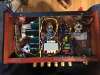
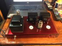
I am attaching the picture of my prototype; don't mind wiring, it is for my schematic. You can see there how to put transformers and other stuff together.
Hi!
The chassis is good, transformers are (surprise!) good too, but however, no instruction!
You can find similar amps in ePay, already assembled, and see pictures, how it supposed to be wired underneath.
I used some parts only, with my own schematic & design, so it would not help you.
I can attach mine, but it is pretty different from the kit.
Some tips.
1. You have to insulate bolts in the transformer to remove the shorted turn that they cause. Remove them, add plastic T-nuts, and heatshrink tubing on them, then put them back.
2. Discard that steel bars that are bolted under the transformer, use M4 nuts instead, to make some vent hole between the chassis and the transformer.
3. There is a tiny PCB supplied for the volume potentiometer. You have to mount it from the "opposite side", i.e. it had to stand on the side with traces, otherwise volume control would work counter-clockwise.
4. Remove bolts from the power switch, better solder wires to it's contacts, bend contacts inside, so they do not damage the transformer.
5. Put rubber washers in holes for leads for output transformers.
6. Using a sharpie, through holes for screws mark wooden sides, for drilling.
Use a drill bit about 2 mm, put some tubing on it, so you don't drill wooden sides through. Pre-drill holes for screws, or you will not be able to screw them into a hard wood. Attach wooden sides.
7. Attach power socket, binding posts, input sockets to the rear panel. Input sockets need additional washers, because they are made for thicker panel.
8. Now you can mount transformers.
Output transformers and a choke are mounted using 4 m4 bolts. One bolt is for a choke only. One bolt is for both socket and one transformer. One bolt is for both transformers. And one bolt is for the transformer only. It is a bit tricky, but you will find how to mount them.
After you bolt all together, you can start soldering. Binding posts are made with insulators from thermo-plastic plastic, so after soldering you will need to tighten them again, and even probably glue from under the chassis, so they do not rotate when you attach speaker cables.
I am attaching the picture of my prototype; don't mind wiring, it is for my schematic. You can see there how to put transformers and other stuff together.
Attachments
Chinese 6P3P, surprise-surprise, is even closer to original RCA 6L6G than Soviet 6P3S, and they are more consistent than Soviet 6P3S. I could match 6 pairs better than 1% from 12 tubes I had. Now I am selling them on ePay already matched.
The kit actually contains Soviet 5Z4S tubes, I am selling them on ePay too, since I use solid state rectifiers only.
6N1 tubes I did not test; I can only repeat what I read online that they are inferior to Soviet 6N1P tubes, but I am absolutely not sure! They may be bad, but may be good, I do not know.
I'd keep going if it were me. You have all the parts necessary and there are plenty of resources available here to help you get through the build.
It doesn't necessarily matter that the design might not be the best - it was $140 after all - but when it is up and running you'll get the sweet satisfaction of bringing an amp to life. Think of the $140 as a learning opportunity.
The schematic is the roadmap. All you need to do is be methodical when wiring and have a read of some of the 'tube amp wiring guides' available on the internet and you'll be alright!
Agree. It is the best way to go. Follow the schematic, assemble as-is, then you will listen to suggestions of venerable Gurus and try to follow them, testing if and how they improve the sound, after your amp is up and running.
Lotus78, you are obviously frustrated, but imho it isn't appropriate to blame others for your frustration, or denigrate what was provided. Many a half finished electronics project has ended up on an internet sales site like ebay.
Even if you kept going with this new found hobby, you would likely modify the amp each time you put it on the bench using whatever knowledge and awareness you had picked up since last you had a look at the amp.
Even if you kept going with this new found hobby, you would likely modify the amp each time you put it on the bench using whatever knowledge and awareness you had picked up since last you had a look at the amp.
Lotus78, you are obviously frustrated, but imho it isn't appropriate to blame others for your frustration, or denigrate what was provided.
Wait..what did I miss??
I was about to add more to this thread but I might hold off for the mo and come back later.
Wow. A reminder why I never post to online forums.
Not really frustrated just taking everything very slow. Checking everything multiple times and making sure I understand what is the purpose of every part.
Sorry did not mean to offend or blame anyone or denigrate anything. The main purpose of the thread was to get opinions if the amp this worth finishing and everyone was very helpful.
Thanks for the wealth of info provided it will take a while to digest.
Good luck to all.
The main purpose of the thread was to get opinions if the amp this worth finishing and everyone was very helpful.
Anatoly (Wavebourn) provided some crucial info. The magnetics are decent, as long as the shorted turn issue is dealt with. Decent "iron" and useful power O/P add up to (IMO) a project worth finishing.
Help is available here for dealing with vendor design flaws and general construction matters. Take your time and see things through.
- Status
- This old topic is closed. If you want to reopen this topic, contact a moderator using the "Report Post" button.
- Home
- Amplifiers
- Tubes / Valves
- Another Newbie Who Bought a Cheap Chinese Tube Amp Kit