Grab one, lose the rectifier tube, go solid-state diodes, and put in an 0D3 in it's place. Set up a pair of sweep tubes per amp, and run them push-pull with fixed bias with a small backwards filament transformer off of the rectifier tube filament winding for the bias supply. Use a high-mu tube up front to get some headroom for feedback. Shove a mosfet in there to feed the grid if you like, the complexity is barely changed ")
You'll end up with a very, very nice amplifier, that wont break the bank, and will be very linear, have great bass performance, and look fancy
You'll end up with a very, very nice amplifier, that wont break the bank, and will be very linear, have great bass performance, and look fancy
Grab one, lose the rectifier tube, go solid-state diodes, and put in an 0D3 in it's place. Set up a pair of sweep tubes per amp, and run them push-pull with fixed bias with a small backwards filament transformer off of the rectifier tube filament winding for the bias supply. Use a high-mu tube up front to get some headroom for feedback. Shove a mosfet in there to feed the grid if you like, the complexity is barely changed
You'll end up with a very, very nice amplifier, that wont break the bank, and will be very linear, have great bass performance, and look fancy
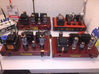
You almost described my first Edelweiss-3 prototypes.
Attachments
Lingwendil,
If you want to make a push pull mono-block amp off of All the original parts (and just a few resistors more), then you can do that.
Build a phase splitter out of the dual triode.
The in-phase splitter output drives one output tube.
The out-of-phase splitter output drives the other output tube.
Let each output tube drive it's original output transformer.
Reverse the Plate and B+ leads of one (only 1) output transformer primary.
Connect the 2 output transformer's taps this way:
two Commons together,
two 4 Ohms together,
and two 8 Ohms together.
Connect your 4, 6, and 8 Ohm loudspeakers from the 8 Ohm tap to the Common tap.
Wala . . . Push pull. More power, less 2nd Harmonic distortion, less 2nd order Intermodulation distortion.
Yes, that is not as good as using a real push pull output transformer, but it did not require a purchase of anything other than a handful of resistors.
Wavebourn,
I really like your Edelweiss amps, and your posts.
But, my post # 83 was the least parts change, least expensive way to get those simple amps to be push pull (if only a mono-block, so 2 simple amps are required to get to push pull stereo).
And Yes, I like both SE and push pull amps.
*** But the easiest way to convert any of those simple SE stereo amps into an SE mono-block is to use a few pieces of wire:
Wire up the amp as was originally designed.
Then:
Wire Left input to Right input.
Wire Common out to Common out.
Wire 4 tap to 4 tap.
Wire 8 tap to 8 tap.
Wire the speaker from 8 tap to Common.
You should get a better damping factor, and lower distortion this way, than driving the same speaker from a single SE amp of this design.
Many 8 Ohm speakers have minimum impedances of 6 or 4 Ohms (the parallel SE and 8 Ohm tap works great for that).
'Just sayin'
And . . . I have actually used SE OPTs and identical SE amps, but with one OPT primary connections reversed; C, 4, and 8 Taps connected together, and used a phase splitter's outputs to drive the L and R inputs.
Not the most efficient or best way to do things, but sounds good in spite of the disadvantages. Just like post # 83.
*** I also have paralleled two identical SE amps, by simply wiring the inputs and outputs as described above to get PSE. Not the most efficient or best way to do things, but sounds good in spite of the disadvantages. And if you have 16 Ohm taps, wire them together, and try connecting the 8 Ohm speaker from the 16 Ohm tap to Common.
All other things being equal, you will get 2X the power.
Last edited:
Hi all,
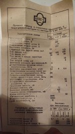
just found this thread. Caught an almost similar kit after spending useless time on the internet (always dangerous) and built it as a sideway-project to my EL84 BH.
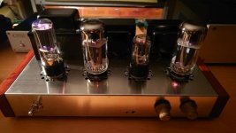
Originally it should come with Chinese 6L6W-GB, 6H9P and 5U4S. As I'm a fan of Russian tubes, I simultaneously ordered a set of Reflektor 6P3S-E and the others. Big surprise, as the kit already came with Russian 6H9P / 5U4S, but Shuguang 6L6W-GB.
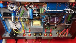
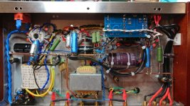
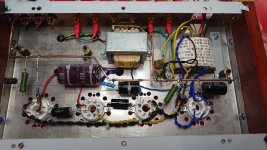
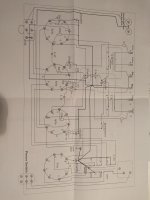
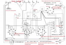
Didn't find any big issues in the schematic and for that just put it together. Some minor tweaks were a 3mm copper wire working as ground (see pictures), better caps, heater symm. and an additional load cap. Ground has been connected to earth via a 100 R and a 100nF Y cap. It was planned to give the amp to a colleague afterwards, so I put in 2 additional RCA with manual source selector and a motorized ALPS-Poti.
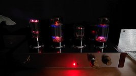
Sound was quite OK with original tubes and schematic. I played a little bit around with FB (now 15k) and caps in the cathode circuit, but the biggest improvement by way was to put in the Russian Ladies.
Do not have the measurements at hand, but roughly 7 W @ 8 Ohms, no hum at all and really "fluid sounding" - do not find a better word. The Odeons with 93 dB SPL really get kicked by this little buddy. Temperature of the iron in the back is still inside the limits. After 1 hour approx 42°C (IR).
To cut it short: Worth, to put it together and let it sing, especially for the price. There are many options to make it better afterwards, and as one can see, the experts here will always find a way to push it even higher and higher.
BTW: No, my colleague still has to wait. This little guy will stay for a while.
just found this thread. Caught an almost similar kit after spending useless time on the internet (always dangerous) and built it as a sideway-project to my EL84 BH.
Originally it should come with Chinese 6L6W-GB, 6H9P and 5U4S. As I'm a fan of Russian tubes, I simultaneously ordered a set of Reflektor 6P3S-E and the others. Big surprise, as the kit already came with Russian 6H9P / 5U4S, but Shuguang 6L6W-GB.
Didn't find any big issues in the schematic and for that just put it together. Some minor tweaks were a 3mm copper wire working as ground (see pictures), better caps, heater symm. and an additional load cap. Ground has been connected to earth via a 100 R and a 100nF Y cap. It was planned to give the amp to a colleague afterwards, so I put in 2 additional RCA with manual source selector and a motorized ALPS-Poti.
Sound was quite OK with original tubes and schematic. I played a little bit around with FB (now 15k) and caps in the cathode circuit, but the biggest improvement by way was to put in the Russian Ladies.
Do not have the measurements at hand, but roughly 7 W @ 8 Ohms, no hum at all and really "fluid sounding" - do not find a better word. The Odeons with 93 dB SPL really get kicked by this little buddy. Temperature of the iron in the back is still inside the limits. After 1 hour approx 42°C (IR).
To cut it short: Worth, to put it together and let it sing, especially for the price. There are many options to make it better afterwards, and as one can see, the experts here will always find a way to push it even higher and higher
.BTW: No, my colleague still has to wait. This little guy will stay for a while
.Attachments
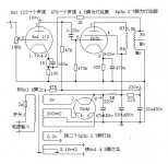
Folks, my rectifier tube was to be 5z4p from kit, but looks like 5U4C on the tube...any concerns?
Chinese 5Z4P is a copy of Soviet 5Ц4С tube, no worries here.
These were from mine...seems they juggle the values a little on feedback and other bits? Since I'm on 120V, voltages seemed a little higher off the bare transformer.
330uF cap only measured 252uF...may seek replacement.
(Thanks for the rectifier touchback.)
330uF cap only measured 252uF...may seek replacement.
(Thanks for the rectifier touchback.)
Attachments
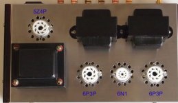
So, mine arrived a few minutes ago - the power transformer has a 110 volt primary, as depicted in most of the pictures of these things. My line normally runs around 120-123 so that will give me a bit of B+ boost.
It has straight sided power tubes, marked as Shuguang 6L6WGB, instead of the small coke bottles in the advertising picture, and a straight sided Russian rectifier. The 6N1 is Shuguang, but without the trade dress.
All the major parts look to be there - iron, punched chassis, tubes, didn't root around in the box for anything else. May or may not have a schematic, not that that matters much.
Still looks like a good deal for the $116 USD or so these are selling for.
I hadn't thought much about the frequency, but it is a pretty good chunk of iron - probably is a 50 Hz part.
I thought I might do like you suggested in another thread - double it for high B+, use undoubled as low B+, and pull a screen voltage out of that. Maybe stick some 6146 in it.
I thought I might do like you suggested in another thread - double it for high B+, use undoubled as low B+, and pull a screen voltage out of that. Maybe stick some 6146 in it.
So I ordered one last week. For about $115 shipped, it's not a bad deal. I'll be building it as a triode output with no global feedback and re-working most everything else as well. I'll document it in another thread, but for now, my initial impressions:
1. It's small. Real small. The length/width is about that of a sheet of paper.
2. The iron is close together. Like sharing the same mounting screws close together. I'm a bit worried about magnetic coupling, but we'll see.
3. The power transformer seems to be big enough, from initial mass estimates.
4. The sheetmetal is SHARP. I sliced open my thumb within the first minute of unboxing. Five minutes with a bastard file and some sandpaper and now it's only mildly dangerous.
5. The packaging was excellent for the price point. No bespoke foam liners (naturally), but lots of foam and thick cardboard around everything.
6. The components look to be quite value oriented. Most everything but the iron, chassis, hardware, sockets, tubes, and maybe the power switch will go into the "use, but not on something critical" spare parts bin. All the components I use will be from my massive parts stash.
7. The output transformers are small for SE. Maybe half the size of my Edcor 25w P-P transformers. So maybe 5w max in SE?
- Status
- This old topic is closed. If you want to reopen this topic, contact a moderator using the "Report Post" button.
- Home
- Amplifiers
- Tubes / Valves
- Another Newbie Who Bought a Cheap Chinese Tube Amp Kit