I am in the process of building a Mullard 3-3 stereo.
After completing the build, the troubleshooting started, and now I have a quite functional amp.
One interesting thing I found is the difference in voltage measurements between the JJ EF806S tubes.
I happen to have 3 new tubes (keep one in reserve) and two of them give voltages different from the other one, while this third one gives voltages in the range of wat is specified by the mullard book. To summarize, here are the voltages:
1 2 3 Expected value
Anode 28V 29V 19V 20V
Screen 33V 33V 26V 28V
Swapping the EL84's don't seem to make any difference.
They seem to amplify fine (I don't have the equipment for measuring the spectrum)
Does anybody have similar experiences?
My guess is that this differences will occur with any ef86 tube. What circuit are you refering to where these voltages occur ? ( never mind i got the mullard doc)
Last edited:
Direct coupling to the EL84.
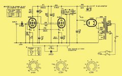
Whole thing is here: Mullard 3-3. Three Watt Amplifier
Whole thing is here: Mullard 3-3. Three Watt Amplifier
Attachments
Last edited:
First of all, changing R4 changes the bias on the EF806S. It should have been done with
R4 the same resistance for all speaker impedances, and change R6 and C5 according to the OPT output Z and the speaker Z.
Then there is the problem that if the EL84 current changes the EL84 self bias voltage changes, which changes the voltage to the screen of the EF806S.
This is a great way (bad way) to amplify the differences in EF806S, and the differences in EL84.
DC coupling can sometimes be simple. DC coupling has some advantage(s).
DC coupling and getting stable and predictable DC voltages is not easy.
They did not succeed in this particular design.
Now you know why I do not use DC coupling.
Make things as simple as possible, but no simpler.
Last edited:
...to have 3 new tubes (keep one in reserve) and two of them give voltages different from the other one, while this third one gives voltages in the range of wat is specified
This is o.k.
The EF86 works with grid leak bias.
Andreas
Thank you for your ideas and the insight that the concept of the Mullard 3-3 amplifies differences between the tubes. The EL84's are a matched pair, hence their difference is limited. The EF806s's are not giving this difference.
The EF86 in this one are operated in starvation mode intentionally. Changing R4 would require me to recalculate the feedback loop and also recalculate (and also resolder) the R6/C5 combination when fiddling around. This is not unsolvable. I happen to have done the calculation a few days ago for a next project involving a mullard 5-10 with the EF86 triode strapped.
I think that I will fiddle around with diffeerent brand of tubes first and keep the JJ's for that later project. What I do notice is that the higher bias voltage seems to cause extra current consumption, since it drops my power cap by a few volts.
Correct.
A particular EL84 that intrinsically draws more current, causes the EF86 screen voltage to go higher, causing the EF86 plate voltage to go down, causing the EL84 current to go down. Correct, that is negative feedback.
A particular EF86 that intrinsically draws more current, causes the EL84 grid voltage to go lower, causing the EL84 current to go down, causing the EF86 screen voltage to go down, causing the EF86 to draw less current. Correct, that is negative feedback.
And the inverse of the above are true, for EF86 and EL84 tubes that intrinsically draw less current. The negative feedback still applies.
That is all good and well. But I believe there is not enough negative feedback to make the voltages of all EF86s and all EL84s be equal in that circuit, especially at such low voltage on the screen and low voltage on the plate of the EF86. In my opinion, the EF86 in that circuit is starved for voltage and starved for current. The reason for starving the EF86 plate voltage was to 'easily' get the grid voltage of the EL84 not be too high (a disadvantage of DC coupling, just what I do not like, woopty do)
Therefore, as Essay observed, the voltages on one EF86 was far different. I would not throw out any of the 3 tubes, at least not unless they were tested at more traditional voltages and currents of the screen and plate.
Hmm, I wonder if Mullard wanted customers to purchase matched EF86 / EL84 sets for this amplifier. Could be a marketing/sales opportunity.
As to grid leak bias, I never liked it. And 10 Meg Ohms grid resistor sounds like it was selected not only for bias, but also to load a high output Crystal Phono pickup. In that case, make sure there is not much capacitance in the shielded wire from the Crystal phono pickup to the EF86 grid; there probably already is enough capacitance in the Crystal to roll off the high frequencies.
And with grid leak bias, make sure that the signal voltage does not overcome the bias voltage, and cause grid current.
Last edited:
Swapping the EL84's don't seem to make any difference.
Do you mean the voltages move with the tubes or that they stay with the circuit positions?
I believe there is not enough negative feedback to make the voltages of all EF86s and all EL84s be equal in that circuit, especially at such low voltage on the screen and low voltage on the plate of the EF86.
The lower the G2 voltage, the *higher* the voltage gain, as long as you have enough current to swing the load.
With 1Meg load to naked grid, gain may be quite high.
(thumbs busy) Ah, with values shown, it is just-barely in NFB, but also has 0.1V input sensitivity which we don't need. The 6.8K could be reduced to 2K or even 1K and gain some real NFB.
The variations in bias-point amount to +/-15% on the power tube, which is not a big deal for such a simple clean circuit-- all tube-work can be +/-20%. The different voltages on the driver are inconsequential.
Member
Joined 2009
Paid Member
Since this is my first tube project, I suspected my soldering to be the culprit.This is why I switched the tagboard between left and right. I used the opportunity to also tidy up the grounding and some other soldering. Turns out that this did not have the expected effect (voltages L and R remained the same).
Then I started switching the tubes around starting with the EL84. Swapping the L and R EL84 did not change the voltages. Swapping the EF806S did move the voltages which means that I found my culprit.
I think that I will order a pair of EH EF86s and see what that gives (NOS Mullards are too expensive for my taste).
")
I have received a matched pair of Svetlana NOS 6J32P and interestingly, one of the tubes features the voltages as indicated by Mullard while the other one features the deviating voltages as seen on 2 of my 3 JJEF806S tubes. They are related to the Svetlanas as switching them switches the voltages.
petertub, regarding your post # 18:
Essay, Read all the below, but especially my opinion 3 below:
petertub . . . Even though there is Some compensating effect of the DC negative feedback from the cathode of the EL84 to the EF86 screen, if you adjust R4, it will do two things:
1. Adjusting R4 for 20/28V on what will now become a new 'unknown' resistance value, will change the EF86 current to a new unknown value. And since the EF86 plate load is 1Meg Ohm, its plate voltage will also be at a new unknown value. It will change the grid voltage on the EL84, and so it will change the plate current of the EL84 to a new unknown value. So much for DC coupled that is fixed by "Compensating' by using DC negative feedback.
2. Adjusting R4 will change the level of AC (signal) negative feedback. How many dB? Too little, and so too little distortion reduction? Too little, and so the damping factor is too low? Too much, and so it is no longer stable, perhaps ringing or even oscillating?
Essay . . .
3. In my opinion, I am disappointed that Mullard actually published that amplifier schematic. It appears to tarnish or ruin Mullard's otherwise good reputation. In their attempt to "Make things as simple as possible, but no simpler", Mullard appears to have crossed the line by trying to 'make it simpler than possible'.
There are lots of circuits (even simple ones) that use an EF86 and EL84 that do not have so many problems, or do not need you to select tubes that work. You have the basic parts: power transformer, output transformer, EF86, EL84, etc.
You either need to be willing to select tubes (the Mullard amp), Or you ought to try another tried and true circuit with the same tubes.
- Status
- This old topic is closed. If you want to reopen this topic, contact a moderator using the "Report Post" button.
- Home
- Amplifiers
- Tubes / Valves
- Difference in JJ EF806S