Hello!
I was wondering is it possible to use 6N7 tube as a push-pull driver stage? 6N7 is a dual triode, datasheet can be found here. Datasheet seems to instruct to connect both grids together for SE operation but I do not understand why?

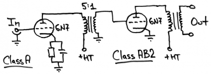
What I would rather want is this (tube is biased as instructed with -TB):

The reason I want the push-pull configuration is that there wouldn't be DC current in the interstage transformer T2 primary which makes it much easier to find one. Any ideas or suggestions why it wouldn't work are welcome.
Thanks,
Igor.
I was wondering is it possible to use 6N7 tube as a push-pull driver stage? 6N7 is a dual triode, datasheet can be found here. Datasheet seems to instruct to connect both grids together for SE operation but I do not understand why?
What I would rather want is this (tube is biased as instructed with -TB):
The reason I want the push-pull configuration is that there wouldn't be DC current in the interstage transformer T2 primary which makes it much easier to find one. Any ideas or suggestions why it wouldn't work are welcome.
Thanks,
Igor.
Last edited:
Data sheet seems to instruct to connect both grids together for SE operation but I do not understand why?
Just to get higher Gm and lower plate resistance.
My opinion is that 6SN7 is better as a driver.
Yeah, 6SN7 makes more sense, but 6N7 is cheap and different. Comes in "G" bottle styles, too ")
It's a pretty good valve though-
http://www.bartola.co.uk/valves/2012/06/17/6n7-as-a-driver/
It's a pretty good valve though-
http://www.bartola.co.uk/valves/2012/06/17/6n7-as-a-driver/
Thanks everyone for the responses!
I was thinking about a step-up line level audio splitter transformer i.e. 600:15K C.T. but I don't know if that's a good idea?
For example I'm not even sure if I have to use grid resistors in this configuration? Also, is cathode biasing here would be a good idea?
Sorry for stupid questions
Actually in the output stage I plan to use same 6N7 tubes in push-pull class B with zero grid bias. Their datasheet explicitly suggests you can use 6N7 to drive 6N7.They were originally meant for class B operation, but work well in class A. They also work well for output devices in their own right, but you're a bit limited by the single cathode.
I have no reservations against 6SN7 as well, my only concern is that with my input RMS of 0.75V I will have a hard time driving it.6SN7 is better as a driver
I was thinking about a step-up line level audio splitter transformer i.e. 600:15K C.T. but I don't know if that's a good idea?
Mostly because this way it's less parts and simpler design. My knowledge is very limited so I would rather parasite on someone's schematics.Why not use it in a long tail pair?
For example I'm not even sure if I have to use grid resistors in this configuration? Also, is cathode biasing here would be a good idea?
Sorry for stupid questions
6n7 Class b
No need for inter-stage
No need for 12AX7. As drawn, the sensitivity would be enormous.
^ yeah that's insane! May as well incorporate tone controls and plug in a guitar!
For typical signal levels something like a 6DJ8 or 6N1P gain/concertina feeding a 6N7 differential, then feeding 6N7 outputs (with a bit of global negative feedback) may be plenty.
This tube at any reasonable output levels will draw grid current if you put it into a lower distortion, lower output, class A operating point. Hence the interstage transformers you often see in uses where they are used as output tubes. Needs a stiff, high current grid driver, and it may be a good option for a hybrid design in the front end... it seems useful for musical instrument amplification.
Last edited:
T
I have no reservations against 6SN7 as well, my only concern is that with my input RMS of 0.75V I will have a hard time driving it.
Sorry for stupid questions
Why? What are you driving it with? If it's a matter of a smaller than 0.75V signal, maybe a 6SL7 would work better for you?
The only stupid question is the one that wasn't asked IMHO. You're in good hands in this forum.
Thanks for the support
But generally speaking, is it an acceptable practice to boost signal with a step up line level transformer? Like this one for example Edcor WSM 600:10k.
Yeah, actually this one looks very promising and is much more sensitive than 6N7 or 6SN7, thanks! I'm driving it from DAC that has 0.75V RMS.If it's a matter of a smaller than 0.75V signal, maybe a 6SL7 would work better for you?
But generally speaking, is it an acceptable practice to boost signal with a step up line level transformer? Like this one for example Edcor WSM 600:10k.
...Datasheet seems to instruct to connect both grids together for SE operation but I do not understand why?...
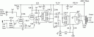
Look at the whole plan.
They already sold you a 6N7 because one tube can make 10 Watts of output.... but zero-bias and high grid current.
This means you need a driver which can deliver high grid current. They sell you another 6N7 (he-he). Working with nice -6V bias you need both sections to get 7mA total plate current.
http://www.mif.pg.gda.pl/homepages/frank/sheets/093/6/6N7.pdf is a better datasheet. As a 10-Watt power amp it needs 22mA peak grid current. With the 5:1 grid transformer this is 5mA from the driver. 5mA peak from 7mA bias is OK distortion; using half the 6N7 driver would be gross distortion *for this configuration*.
But the GE data also has single-section R-C coupled data. The top line, at 300V, will flog most ordinary (not class 2) outputs to their limits just fine.
When 6N7 was designed there were only classes A and B for audio. What they called class B in the datasheet, today would be called Class AB2, with 35 mA idle anode current.
To drive it you need 22 mA, 41V peak per each triode. That translates into 0.45W per triode, or 0.9W to get 10W output power on 8K P-P load with 300V B+.
To drive it you need 22 mA, 41V peak per each triode. That translates into 0.45W per triode, or 0.9W to get 10W output power on 8K P-P load with 300V B+.
Thanks for the support
Yeah, actually this one looks very promising and is much more sensitive than 6N7 or 6SN7, thanks! I'm driving it from DAC that has 0.75V RMS.
But generally speaking, is it an acceptable practice to boost signal with a step up line level transformer? Like this one for example Edcor WSM 600:10k.
You can, but most people find it cheaper, easier, and with less distortion to use another tube stage instead.
OK, thanks everyone, it's becoming more clear now.
Now I'm struggling to understand the interstage transformer coupling when driving the class AB2. It's apparently very different to driving speakers or class A. Let's imagine I use the suggested 5:1 transformer.
1. What is the reflected impedance that primary sees in this configuration? Datasheet specifies effective Grid-Circuit impedance of 516 Ohm in class B, so that would give me 516*5^2=12.9k Ohm on primary, is that correct?
2. If I were to deliver 22mA and 41V peak to the grid, it means I have to develop about 22/5=4.4mA and 41*5=205V peak on the primary, is that correct?
3. But if primary is effectively 12.9k Ohm load then driving 4.5mA through it would result in only 56.7V drop. Or do I have to develop at least 205V by driving at least 15.9mA through the primary?
I'm confused here. My math is obviously wrong but I cannot figure out where exactly.
Any help is appreciated
Attachments
As a 10-Watt power amp it needs 22mA peak grid current. With the 5:1 grid transformer this is 5mA from the driver.
Alright, but it also requires 200V peak on the primary, I cannot see how designers expect to achieve that given the grid curves.


And using transformer coupling will bring plate voltage to much more than 300V max specified for this tube, is that even allowed?
> using transformer coupling will bring plate voltage to much more than 300V max specified for this tube, is that even allowed?
The DC plate voltage is still 300V.
The signal swings lower just as much as it swings higher. Tube abuse does not change. (No, 500+V peaks will not cause sparks.)
The 512 Ohms is the "source". This appears to be the ~~10K plate resistance divided by the impedance transformation. The load is evidently 41V/22mA or 2K.
- Status
- This old topic is closed. If you want to reopen this topic, contact a moderator using the "Report Post" button.
- Home
- Amplifiers
- Tubes / Valves
- 6N7 as push-pull driver