I was brainstorming dead-simple amps to make as stocking stuffers this Christmas, and reviewing data sheets for the tubes I have lying about.
What I came up with is too simple to be true, so what is my mistake!
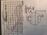
B+ 180V (house voltage, isolation, full-wave diode)
Tube 829B
Bias 0V
Screen Ultra Linear
OPT 600 Ohms (300 if both segments are in parallel)
Known issues:
Input V will be limited to about 20V to avoid very non-linear response
The OPT will be hard to find
The screen will not be the norm of 200V for this tube as I am using UL from B+ of 180 so power will be lower than my sketch shows...
But I must have missed something worse than these issues
What I came up with is too simple to be true, so what is my mistake!
B+ 180V (house voltage, isolation, full-wave diode)
Tube 829B
Bias 0V
Screen Ultra Linear
OPT 600 Ohms (300 if both segments are in parallel)
Known issues:
Input V will be limited to about 20V to avoid very non-linear response
The OPT will be hard to find
The screen will not be the norm of 200V for this tube as I am using UL from B+ of 180 so power will be lower than my sketch shows...
But I must have missed something worse than these issues
Attachments
The Plate pins and full HV are on top, exposed. Unless you are sure your giftee will never have kids or cats in the house, this is too reckless.
On the face of it, a 40W tube SE amp needs BIG OT and PT; will rip the stocking off the wall. I would not even want to ship it.
I would not worry about "limited to about 20V", it will be real ******* loud before that.
But you do need +/-20V drive to get full output. Sources are typically 1V. It needs a gain stage.
BUT you are taking the grid +positive+. Grid impedance will be infinite on the down-swing and fall to 300 Ohms at peak up-swing. No simple tube driver will do this gross change of load without extreme THD. It is at the upper limit of chips. This sure can be patched-over somehow, but you clearly have a lot of thinking ahead of you. More than I would commit-to in 5 weeks. Fails the "dead simple" criteria.
In hindsight the 829 was a diversion from my primary question.
It seems the norm is to use high voltage and high load to get a horizontal load line to limit plate dissipation and cross as many of the grid voltage curves as possible. This maximizes the output of the tube.
I wanted to test the logic of using an oversized tube so that it could be run at low voltage (simple power supply) and 0 bias (simple circuit). I was just pursuing the elegance of simplicity, like a single-speed bike.
The data sheets for triodes do not even show V+ bias curves, so it was obvious that this was not an option. But I made the (apparently faulty) assumption that when the pentode data sheets showed + curves that G1 was allowed to accelerate the electrons as well as suppress them. If not, what are the + bias curves shown for? There must be some other application?
Many triode datasheets show positive grid curves.
http://www.mif.pg.gda.pl/homepages/frank/sheets/093/1/12AU7A.pdf
Bottom page 4.
If you take G1 to +30V, and Vp falls to 30V, you get 100mA in Plate *and* 100mA in G1.
The instantaneous grid impedance at this point is about 30V/100mA or 300 Ohms. Contrast to the >100Meg at the other end of the audio swing when grid is negative.
You hang a child's swing. One way it swings into free space, moves easy. The other way it swings into a sand-pile, swings hard. It will be difficult to get a smooth reproduction of an arbitrary analog waveform when one side is free and the other is a drag.
Why would you do this? In Radio Frequency work we can use tuned circuits to store-up energy over a whole cycle to supply a burst at the positive peak. The residual distortion is easily tuned out of the output. There are less extreme examples at the fringes of audio.
- Status
- This old topic is closed. If you want to reopen this topic, contact a moderator using the "Report Post" button.
- Home
- Amplifiers
- Tubes / Valves
- Simple 829 SE Amp