Hi everyone
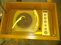
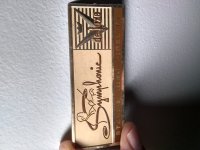
I am looking for help in bringing a tube amp I bought in flea market back to life. It was part of a turntable console by a company called "Symphonic". I dismantled carefully and brought the turntable and the amp in. I am a fairly newbie to valve electronics - have some experience with microcontrollers, simple discrete circuits like rectifier bridges, h bridges for controlling dc motors etc. I guess none of my pitifully small knowledge will help me here with the grownup world of valves.
I am hoping to bring it back to life, took lots of pictures so I know where things should go just in case. I understand that all the electrolytic caps must go! I have been looking at the circuit underneath and can't figure out what capacitors to order. I am assuming I need to change to Can capacitor too that is on the top of the circuit.
Also, once I put the new caps in, is it ok to power it on or should I use a current limiter as described by "uncle doug" on youtube? I have a simple multimeter. I don't have a variac. I have a reasonable soldering equipment. I will put some pictures. Is there anyone who is willing to kindly handhold and guide me through this process?
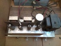
Main power transformer has "TR180", 831022 on it. It has one EZ81/6030, two of EL84/6BQ5/6035, one of ECC83/6030.
Sorry about haphazard info and lots of questions. Thanks in advance.
I am looking for help in bringing a tube amp I bought in flea market back to life. It was part of a turntable console by a company called "Symphonic". I dismantled carefully and brought the turntable and the amp in. I am a fairly newbie to valve electronics - have some experience with microcontrollers, simple discrete circuits like rectifier bridges, h bridges for controlling dc motors etc. I guess none of my pitifully small knowledge will help me here with the grownup world of valves.
I am hoping to bring it back to life, took lots of pictures so I know where things should go just in case. I understand that all the electrolytic caps must go! I have been looking at the circuit underneath and can't figure out what capacitors to order. I am assuming I need to change to Can capacitor too that is on the top of the circuit.
Also, once I put the new caps in, is it ok to power it on or should I use a current limiter as described by "uncle doug" on youtube? I have a simple multimeter. I don't have a variac. I have a reasonable soldering equipment. I will put some pictures. Is there anyone who is willing to kindly handhold and guide me through this process?
Main power transformer has "TR180", 831022 on it. It has one EZ81/6030, two of EL84/6BQ5/6035, one of ECC83/6030.
Sorry about haphazard info and lots of questions. Thanks in advance.
Attachments
-
 s-IMG_20181117_162119064.jpg326.1 KB · Views: 431
 -
 s-IMG_20181117_200640220.jpg338.7 KB · Views: 423
 -
 s-IMG_20181117_192931560.jpg632.7 KB · Views: 430
 -
 s-IMG_20181117_200703162.jpg422.7 KB · Views: 410
 -
 s-IMG_20181117_200706149.jpg421.6 KB · Views: 408
 -
 s-IMG_20181117_201059725_HDR.jpg333.5 KB · Views: 164
 -
 s-IMG_20181117_200828620.jpg468.6 KB · Views: 153
It's cheap, but (fortunately) not dangerously so. ") A power transformer is present.
A power transformer is present.
The turntable and cartridge are GUANO. They can destroy valuable LPs.
You can refurbish the amp to play "OK", when fed from a CDP or decent TT/cart./phono preamp combo.
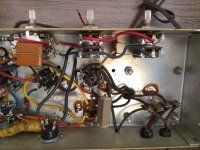
The circuitry is simple single ended 12AX7 section voltage amplifier driving 6BQ5 pentode O/P. It delivers about 5 WPC. The tone controls are utter garbage and have to go. You retain the sheet metal, transformers, and tubes (if they test good). You can clamp mount a nice part in the opening, where the "twistlok" can is currently mounted. A safety grounded, 3 wire, power cord is in order too.
You can look at this Magnavox schematic for ideas about how you rebuild your piece. Instead of a balance pot., use 2 individual volume controls to set listening level and channel to channel balance.
A power transformer is present.The turntable and cartridge are GUANO.
They can destroy valuable LPs.You can refurbish the amp to play "OK", when fed from a CDP or decent TT/cart./phono preamp combo.
The circuitry is simple single ended 12AX7 section voltage amplifier driving 6BQ5 pentode O/P. It delivers about 5 WPC. The tone controls are utter garbage and have to go. You retain the sheet metal, transformers, and tubes (if they test good). You can clamp mount a nice part in the opening, where the "twistlok" can is currently mounted. A safety grounded, 3 wire, power cord is in order too.
You can look at this Magnavox schematic for ideas about how you rebuild your piece. Instead of a balance pot., use 2 individual volume controls to set listening level and channel to channel balance.
Firstly, if you're new to tubes be aware that there is high voltage present, potentially in excess of 400 volts depending on the device. I would expect at least 300 in a device like this. Make sure you understand how to work safely around these kinds of voltages.
You're correct that the electrolytic must go, but of equal importance are the wax coupling capacitors. With age the paper dielectric breaks down and they leak DC across them. All of them MUST go, as they can destroy output tubes and even output transformers. I've seen some very nice equipment destroyed by bad coupling capacitors (A monitor amp from a recording studio, built from a modified heathkit AA-40 and running KT88 tubes).
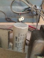
The Multi-section electrolytic can is a PITA to replace, and If I were you I'd disconnect it (DO NOT leave it connected, as it WILL eventually short) and use modern capacitors internally on a terminal strip.
The tubes are likely fine.
That power transformer looks nice and beefy. FWIW, power transformer part numbers are typically (with exceptions) completely useless. You can try googling the part number, but unless it's from a very common piece of equipment (Dynaco or Heathkit), or a catalog part from UTC or Stancor there's a pretty good chance you will turn up nothing.
You're correct that the electrolytic must go, but of equal importance are the wax coupling capacitors. With age the paper dielectric breaks down and they leak DC across them. All of them MUST go, as they can destroy output tubes and even output transformers. I've seen some very nice equipment destroyed by bad coupling capacitors (A monitor amp from a recording studio, built from a modified heathkit AA-40 and running KT88 tubes).
The Multi-section electrolytic can is a PITA to replace, and If I were you I'd disconnect it (DO NOT leave it connected, as it WILL eventually short) and use modern capacitors internally on a terminal strip.
The tubes are likely fine.
That power transformer looks nice and beefy. FWIW, power transformer part numbers are typically (with exceptions) completely useless. You can try googling the part number, but unless it's from a very common piece of equipment (Dynaco or Heathkit), or a catalog part from UTC or Stancor there's a pretty good chance you will turn up nothing.
Last edited:
Power it up on a lamp limiter first and leave it on for a bit, see if the big can cap will reform. It's not necessary to replace all electrolytics at first, those cylindrical caps will almost certainly need replacing, the ceramics should be fine.
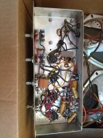
The 0.05 caps can be replaced by 47n or 0.047u 630v rated axial poly caps. Can't see what the other two underneath are.
Give it a go before you rip it apart, once you've learned a bit more you can replace things like tone controls etc.
Some of the resistors may be out of spec, but worry about them later, valve amplifiers are different to tranny amps.
Andy.
That power transformer looks nice and beefy.
Yes, and the 150 mA. capable 6CA4/EZ81 rectifier is more than the circuitry needs. The OEM probably used that pairing with a radio containing model. Economies of scale in inventory control work to the OP's advantage. The power trafo/rectifier are (IMO) the best part of the entire package.
The Multi-section electrolytic can is a PITA to replace, and If I were you I'd disconnect it (DO NOT leave it connected, as it WILL eventually short) and use modern capacitors internally on a terminal strip.
Might as well take advantage of available "real estate" and clamp mount the twin 50 μF./500 WVDC F&T part Jim McShane sells in the hole. Going up in WVDC never causes trouble.
Either 0.047 μF./400 WVDC 716P series Orange Drops or Soviet surplus K40 paper in oil (PIO) parts are highly suitable as replacements for the 0.05 μF./200 WVDC waxed paper parts.
The ceramic disc caps. rate to be intact, but the square, multi-lead, part is a PEC (an early, minimal, integrated circuit) which all too often goes bad. You need the exact OEM schematic in order to learn the values contained and assemble a replacement from discrete parts, when failure has occurred. IMO, there's more than 1 good reason for disposing of tone controls.
Hi everyone
Happy to hear all the opinions.
On another thread I asked for suggestions to get an amp. Following those suggestions I bought a Magnavox 9302-10. It is in the mail. While I was out wandering I happened upon this amp from this thread and bought it to learn. So if I ruin it, at least I will have a power transformer and possibly some tubes to keep spare.
@H713: Thanks for the warning. I have been reading and looking at some of the schematics. While I don't understand schematics well, I did realize that 325VDC probably isn't good for my heart. Also - tried finding the power transformer by number - didn't turn up much.
@KodaBMX: I will probably replace the parts that need to be replaced - like the capacitors and try first. It will be my first valve amp - hopefully not my last.
@EliDuttman:
I thought so about the turntable. I have a modern turntable already. So I might look at this one just for the sake of learning in the future. I will order the orange caps as you and DiabolicalArtificer noted for the waxed paper caps under the tubes. What are the options for the multi lead caps? If I leave them in to start off with, will they cause much damage? If they must go - then perhaps removing the whole tone control stuff is a better option like you said. If that is the case, I will take a closer look and see if I can figure it out / else, more questions!
I will get the twin 50microf/500v and try clamp mounting.
@DiabolicalArtificer: I will make a lamp limiter first. Do you think it is ok to try the can capacitor and see if it will reform? From what little I read, everyone seem to suggest getting rid of it first! Again, I am a total newb so perhaps more cautious.
I am going to make an inventory of the capacitors underneath so I can look for replacements.
Thanks all and have a great sunday.
Happy to hear all the opinions.
On another thread I asked for suggestions to get an amp. Following those suggestions I bought a Magnavox 9302-10. It is in the mail. While I was out wandering I happened upon this amp from this thread and bought it to learn. So if I ruin it, at least I will have a power transformer and possibly some tubes to keep spare.
@H713: Thanks for the warning. I have been reading and looking at some of the schematics. While I don't understand schematics well, I did realize that 325VDC probably isn't good for my heart
. Also - tried finding the power transformer by number - didn't turn up much.@KodaBMX: I will probably replace the parts that need to be replaced - like the capacitors and try first. It will be my first valve amp - hopefully not my last.
@EliDuttman:
I thought so about the turntable. I have a modern turntable already. So I might look at this one just for the sake of learning in the future. I will order the orange caps as you and DiabolicalArtificer noted for the waxed paper caps under the tubes. What are the options for the multi lead caps? If I leave them in to start off with, will they cause much damage? If they must go - then perhaps removing the whole tone control stuff is a better option like you said. If that is the case, I will take a closer look and see if I can figure it out / else, more questions!
I will get the twin 50microf/500v and try clamp mounting.
@DiabolicalArtificer: I will make a lamp limiter first. Do you think it is ok to try the can capacitor and see if it will reform? From what little I read, everyone seem to suggest getting rid of it first! Again, I am a total newb so perhaps more cautious.
I am going to make an inventory of the capacitors underneath so I can look for replacements.
Thanks all and have a great sunday.
I found the following capacitors and resistors.
#2 of 0.05mfd, 200vdc
#2 of 0.25mfd, 200vdc
#2 ERIE 0.1Z Z5U orange caps
I don't know how to read the orange caps with multiple leads.
Also has a 820hm 3W RW35 resistor and a 270ohm 5W RW107 resistor.
I am going to start hunting for the parts now
#2 of 0.05mfd, 200vdc
#2 of 0.25mfd, 200vdc
#2 ERIE 0.1Z Z5U orange caps
I don't know how to read the orange caps with multiple leads.
Also has a 820hm 3W RW35 resistor and a 270ohm 5W RW107 resistor.
I am going to start hunting for the parts now
Hi thulearch - and welcome!
Looks like you're off to a good start, viz.:
Those "multi-legged caps" are (usually) proprietary RC networks for the tone controls. As previously mentioned you'll need the actual schematic to make any real sense out of these. That's why Eli suggested removing them completely, as it eliminates one unknown and a potential source of trouble.
Have fun and keep us posted!
Looks like you're off to a good start, viz.:
- You're beginning like quite a few of us here, namely rehabbing an old console amp. They're simple, forgiving, and "cheap as chips". As an added bonus they tend to use tubes that are still readily available.
- You attached clear, relevant pictures to your first post, which led to...
- Excellent advice from everyone responding thus far. Hats off to you, sir!
Those "multi-legged caps" are (usually) proprietary RC networks for the tone controls. As previously mentioned you'll need the actual schematic to make any real sense out of these. That's why Eli suggested removing them completely, as it eliminates one unknown and a potential source of trouble.
Have fun and keep us posted!
Last edited:
Hi Mr_Zenith
Thanks. I was indeed looking to replace the unusual input connections it has. Output seem to go to a simple 3 wire out - I am assuming 2 signal and 1 common.
I am also thinking of removing the tone control since I can't figure out what to do with the multi legged caps. I will post close ups later on and my proposed way of removing the tone controls. Hopefully I won;t make a mess
Also I share the mouser cart here:
First two are options for 0.047mfd, 400vdc.
Second two on the list are options of 0.25mfd, 200vdc
I also found 82 and 270ohm resistors as in the cart. I am not sure what to make of the last one - 0.1Z Z5U - I found the Z5U dielectric and 0.1mfd. Is that the correct one?
Mouser Electronics
Thanks everyone.
For that last cap, I'd recommend one like this (look at the backorder status on the one in your shopping cart). In fact, I'd replace all of the wax ones with ones from this series. If you get squeamish about the lengths of the bare wire leads you can always cover them with heat shrink or pieces of insulation stripped from hookup wire.
Regarding caps in general, tolerances of those wax paper and foil jobs used on most budget sets of that era (like yours) were usually measured within +/- 10 or 20% of the stated value. That's why Diabolical and Eli recommend substituting a new 0.47 for an original 0.50 uF; the difference is insignificant in the scheme of things.
The big problem with those caps is that they absorb moisture over time and become leaky. If the cap in question is used for coupling between stages, this leakage can place a positive DC bias on the control grid of the output stage - which leads to red-plating and eventual tube death. That's why H713 was so adamant about their replacement, and I agree. If you've ever seen one "cook off" you'll never forget it. Besides, they're cheap insurance.
As an aside, many of the old wax paper caps used on 1920's and '30's sets (most notably Zenith) were coated in beeswax, and sometimes you could still smell it when melting it off the cardboard tube even 70 years later(!).
Last edited:
Mr_Zenith,
If you look at the lower right of the 1st underside photo, you'll see a "Cheap Charlie" twin RCA jack on phenolic. They're pretty closely spaced and have to be used with cabling that's terminated with Neutrik/Rean NYS-352G plugs.
If you look at the lower right of the 1st underside photo, you'll see a "Cheap Charlie" twin RCA jack on phenolic. They're pretty closely spaced and have to be used with cabling that's terminated with Neutrik/Rean NYS-352G plugs.
Hi Eli, I believe you're correct. Thanks for pointing that out.
Depending on the angle, it's sometimes difficult to tell these things from pictures. I once recapped an amp from an old RCA console that had a flimsy phenolic 3-pin connector for an input. The inner contacts looked somewhat similar to those on the OP's amp.
The irony was that although the amp was an RCA, there wasn't an RCA jack anywhere on the chassis!
Last edited:
Mr_Zenith,
If you look at the lower right of the 1st underside photo, you'll see a "Cheap Charlie" twin RCA jack on phenolic. They're pretty closely spaced and have to be used with cabling that's terminated with Neutrik/Rean NYS-352G plugs.
Hi Eli Duttman
That was connected to a stereo out jack on the cabinet that I had cut through.
Thanks for the suggestions.For that last cap, I'd recommend one like this (look at the backorder status on the one in your shopping cart). In fact, I'd replace all of the wax ones with ones from this series. If you get squeamish about the lengths of the bare wire leads you can always cover them with heat shrink or pieces of insulation stripped from hookup wire.
Regarding caps in general, tolerances of those wax paper and foil jobs used on most budget sets of that era (like yours) were usually measured within +/- 10 or 20% of the stated value. That's why Diabolical and Eli recommend substituting a new 0.47 for an original 0.50 uF; the difference is insignificant in the scheme of things.
The big problem with those caps is that they absorb moisture over time and become leaky. If the cap in question is used for coupling between stages, this leakage can place a positive DC bias on the control grid of the output stage - which leads to red-plating and eventual tube death. That's why H713 was so adamant about their replacement, and I agree. If you've ever seen one "cook off" you'll never forget it. Besides, they're cheap insurance.
As an aside, many of the old wax paper caps used on 1920's and '30's sets (most notably Zenith) were coated in beeswax, and sometimes you could still smell it when melting it off the cardboard tube even 70 years later(!).
I found the replacement for the big can - Capacitor - Electrolytic, 50/50 mF @ 500 VDC, F&T: Amazon.com: Industrial & Scientific
Will that work?
Also I was unable to find the 0.25mf - instead found 0.27mf - not sure if this will make a big difference! Mouser Electronics
So that is what the smell was - bees wax - on my fingers!
Thanks
Jim McShane's price for the F&T part is close to the Amazon price and he has the clamp you need. Factor in shipping costs for 2 parcels vs. 1 and buying from Jim seems sensible to me.
Remember, the 20% tolerance of those old capacitors. 8% is the difference between 0.25 μF. and 0.27 μF. That's nothing to get excited over.
Remember, the 20% tolerance of those old capacitors. 8% is the difference between 0.25 μF. and 0.27 μF. That's nothing to get excited over.
I was hoping that is the case with tolerance. I had already emailed Jim McShane too and requested if he can provide / guide the other parts as well. He just replied and I am going to request the parts from him.
On a related note, what is the purpose of the big can capacitor - is it the coupling capacitor between two stages of preamp, i:e; before the grid of the second stage of preamp?
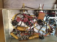
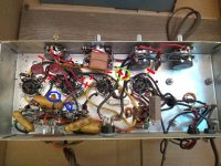
I am thinking of chopping off the tone controls this weekend. I attached an image with some markings. I am sorry about the amateurish markings
The red lines are all the controls that are connected to the pots somehow. Especially the multileg cap and the first pot with the bronze center has a lot of connections.
I can see the input going to the second pot from the right. [red double lines inside green circle] Without the benefit of schematic, can you tell me whether I can do away with all these? If I can, then I guess I don't even need to replace the 0.1mfd orange caps. Somehow the bronze turner makes me think that that is a necessary piece.
If I do remove the pot the input is connected to, then I am guessing the inputs need to go to the preamp tube - - in this case the second one from the left, holding the ecc83 tube.
Also inside the blue circles there are two tiny caps that read "100M" - judging by the size and 3 digit - is it safe to assume that is a 100 picofarad with tolerance of 20%?
Thanks
On a related note, what is the purpose of the big can capacitor - is it the coupling capacitor between two stages of preamp, i:e; before the grid of the second stage of preamp?
I am thinking of chopping off the tone controls this weekend. I attached an image with some markings. I am sorry about the amateurish markings
The red lines are all the controls that are connected to the pots somehow. Especially the multileg cap and the first pot with the bronze center has a lot of connections.
I can see the input going to the second pot from the right. [red double lines inside green circle] Without the benefit of schematic, can you tell me whether I can do away with all these? If I can, then I guess I don't even need to replace the 0.1mfd orange caps. Somehow the bronze turner makes me think that that is a necessary piece.
If I do remove the pot the input is connected to, then I am guessing the inputs need to go to the preamp tube - - in this case the second one from the left, holding the ecc83 tube.
Also inside the blue circles there are two tiny caps that read "100M" - judging by the size and 3 digit - is it safe to assume that is a 100 picofarad with tolerance of 20%?
Thanks
Attachments
The transformer date code is 1960, week 22. That may be enough for me to find a schematic in my files - though a model number or chassis number would be better. Unfortunately, I no longer have a scanner since "upgrading" to Windows 10. But I can find a way to copy it, I'm sure.
Unfortunately, the 100M marking could mean either 100 or 10 pF. In some cases, less than 1000 pf is labeled directly in picofarads. In others it follows the resistor color code - one, zero, followed by zero zeroes. The resistors on the vicinity are 6.8 meg, which means the node is high impedance which would tend to favor smaller cap values. 101M would be unambiguous. I would find some way of measuring one of them if contemplating replacement. There is no reason for them to outright fail, howevrer.
First things 1st. You have a safety issue! Install a proper, 3 wire, correctly "bonded", safety grounded power cable. You don't want that exposed chassis shocking anybody.
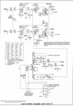
Not having the OEM schematic is "flying blind." FWIW, I'd go with a bastardized version of the Magnavox schematic I linked earlier and am now uploading. That way, all the "extraneous" stuff currently in situ will just occupy space and you don't have to worry about cutting a wrong wire.
R1, R3, & R10 go. R4 & R11 become 100 Ω/1/2 W. carbon composition mounted right at the socket lugs. Connect 100 Kohm log. taper pots. across the I/P jacks, with the wipers connected to the "free" ends of the 100 Ω parts. You will remove the OEM volume and balance controls to make room for the new 100 Kohm parts.
Magnavox (bless them) used a CLC PSU filter. You'll settle for CRC. The twin 50 μF. F&T part McShane sells will fit into the opening currently occupied by the OEM can and is OK for use with your 6CA4/EZ81. All other 'lytics needed will go underneath the chassis top. Modern 'lytics are much more volumetrically efficient than the old time stuff.
The 470 pF. parts, C3 & C5, are for phase compensation. Their value is tied to the O/P transformers in use. Your "iron" is different and you need an oscilloscope plus signal generator to experimentally determine an appropriate value. Leave them out, at least for now. The firm 20 KHz. limit of "Red Book" CD will work to your advantage. Info. above 20 KHz., as provided by phono or HIREZ digital, could be problematic.
Not having the OEM schematic is "flying blind."
FWIW, I'd go with a bastardized version of the Magnavox schematic I linked earlier and am now uploading. That way, all the "extraneous" stuff currently in situ will just occupy space and you don't have to worry about cutting a wrong wire.R1, R3, & R10 go. R4 & R11 become 100 Ω/1/2 W. carbon composition mounted right at the socket lugs. Connect 100 Kohm log. taper pots. across the I/P jacks, with the wipers connected to the "free" ends of the 100 Ω parts. You will remove the OEM volume and balance controls to make room for the new 100 Kohm parts.
Magnavox (bless them) used a CLC PSU filter. You'll settle for CRC. The twin 50 μF. F&T part McShane sells will fit into the opening currently occupied by the OEM can and is OK for use with your 6CA4/EZ81. All other 'lytics needed will go underneath the chassis top. Modern 'lytics are much more volumetrically efficient than the old time stuff.
The 470 pF. parts, C3 & C5, are for phase compensation. Their value is tied to the O/P transformers in use. Your "iron" is different and you need an oscilloscope plus signal generator to experimentally determine an appropriate value. Leave them out, at least for now. The firm 20 KHz. limit of "Red Book" CD will work to your advantage. Info. above 20 KHz., as provided by phono or HIREZ digital, could be problematic.
Attachments
- Status
- This old topic is closed. If you want to reopen this topic, contact a moderator using the "Report Post" button.
- Home
- Amplifiers
- Tubes / Valves
- Looking for guidance to bring an amp back to life