Hi Eli
Thanks for all the suggestions so far. I hope I didn't give an air of having more knowledge than I have") I am learning but certainly need to be cautious on what I do before blowing myself or someone else. So thanks for the warnings. So, some of the questions may sound basic - that's me with caution.
I am learning but certainly need to be cautious on what I do before blowing myself or someone else. So thanks for the warnings. So, some of the questions may sound basic - that's me with caution.
Re: 3 wire, I am going to take out the old power cable and have a 3 prong tail to replace with. Ground goes to chasis and the two other [live and neutral] go to where the old one was feeding. Old one has a plug with same sized blades - so polarity doesn't matter I guess.
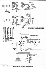
Now to under the hood - from what I understand, I still need to replace the big can and all the wax capacitors and the two resistors as planned. However - I can by pass the tone controls by feeding to the pins number 2 and 7 of the 12AX7/ECC83 preamp - one for each input line, via the 100 ohm resistor and the pot as volume control. Am I understanding it right?
So, since the rest of the connections such as preamp feeding the poweramp, poweramp feeding the output transformer are already in place, I don't need to mess with them. Is that what you meant by the bastardized magnavox?
If that is the case, what should I do with the multi-legged caps - will they not cause problems if they are leaky, even if they are not being used in tone controls?
I know, a lot of questions
Also, I am enclosing a slightly photoshopped [darkened and sharpened version of the schematic you enclosed - a little more readable for my eyes].
Thanks
That will be great. It certainly is a learning experience for me.
Thanks Tom.
Hi wg_ski
In that case, I will leave them as it is and see if they cause pain!
Thanks
Thanks for all the suggestions so far. I hope I didn't give an air of having more knowledge than I have
I am learning but certainly need to be cautious on what I do before blowing myself or someone else. So thanks for the warnings. So, some of the questions may sound basic - that's me with caution.Re: 3 wire, I am going to take out the old power cable and have a 3 prong tail to replace with. Ground goes to chasis and the two other [live and neutral] go to where the old one was feeding. Old one has a plug with same sized blades - so polarity doesn't matter I guess.
Now to under the hood - from what I understand, I still need to replace the big can and all the wax capacitors and the two resistors as planned. However - I can by pass the tone controls by feeding to the pins number 2 and 7 of the 12AX7/ECC83 preamp - one for each input line, via the 100 ohm resistor and the pot as volume control. Am I understanding it right?
So, since the rest of the connections such as preamp feeding the poweramp, poweramp feeding the output transformer are already in place, I don't need to mess with them. Is that what you meant by the bastardized magnavox?
If that is the case, what should I do with the multi-legged caps - will they not cause problems if they are leaky, even if they are not being used in tone controls?
I know, a lot of questions
Also, I am enclosing a slightly photoshopped [darkened and sharpened version of the schematic you enclosed - a little more readable for my eyes].
Thanks
The transformer date code is 1960, week 22. That may be enough for me to find a schematic in my files - though a model number or chassis number would be better. Unfortunately, I no longer have a scanner since "upgrading" to Windows 10. But I can find a way to copy it, I'm sure.
That will be great. It certainly is a learning experience for me.
Thanks Tom.
Unfortunately, the 100M marking could mean either 100 or 10 pF. In some cases, less than 1000 pf is labeled directly in picofarads. In others it follows the resistor color code - one, zero, followed by zero zeroes. The resistors on the vicinity are 6.8 meg, which means the node is high impedance which would tend to favor smaller cap values. 101M would be unambiguous. I would find some way of measuring one of them if contemplating replacement. There is no reason for them to outright fail, howevrer.
Hi wg_ski
In that case, I will leave them as it is and see if they cause pain!
Thanks
Attachments
If some OEM parts are physically present, but out of circuit, they will not cause trouble. Remember the leak being discussed is electrical, not mechanical.
Bastardization means using it as a guideline, not simply copying.
Correct "bonding" of the green (ground) wire requires a ring terminal at the wire's end and mounting said terminal on screw using a lock washer & nut. Nothing else is attached to that screw.
Notice that Magnavox used the chassis for the signal ground. These days, that practice is frowned upon, as it can lead to ground loop hum. Search the archives for discussions of a ground bus. The bus gets connected to the chassis at a single point.
The quality of the O/P transformers is the limiting factor. Those present are not impressive, but you do want to squeeze everything out that they are capable of.
Ok. I will put a ring mount and change to 3 wire power cord.
I did get the electrical leakage part of the capacitors, though some of them seem to leak physically too
My question was about the tone control circuit being present on the side. From what you say if input is not connected to tone control it theoritically shouldn't affect the over all outcome.
Thanks
If you're attaching you own 3 prong grounding plug, remember this rhyme, "White goes to bright" and not the brass one. In America, if everyone did their job correctly, the white/bright will be low side neutral.Re: 3 wire, I am going to take out the old power cable and have a 3 prong tail to replace with. Ground goes to chasis and the two other [live and neutral] go to where the old one was feeding. Old one has a plug with same sized blades - so polarity doesn't matter I guess.
Hi Hollowstate
Isn't the black wire hot, white neutral and green or bare ground? The wire I have is with preformed plug, with one end up connected, I scavenged it from a power cord for laptop, it was accidentally damaged in the middle.
The power connections inside the amp are on a terminal strip.
Thanks
Isn't the black wire hot, white neutral and green or bare ground? The wire I have is with preformed plug, with one end up connected, I scavenged it from a power cord for laptop, it was accidentally damaged in the middle.
The power connections inside the amp are on a terminal strip.
Thanks
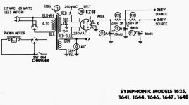
I found a Sams folder that covers four Symphonic models, uses the same four tubes, and power transformer is part number TR-180. (three output transformer #s listed, TR-184, TR-178, TR187 depending on model.) Sounds like we're getting close. But seems off in a number of ways - doesn't have the heat shields, has two four-terminal ceramic RC coupling networks, and doesn't show any three-terminal ones.
The .25 caps and .05 caps are used to shape the frequency response of the feedback network - eliminate them with the tone controls (which are pretty harmless really - will have almost ZERO effect if you're not driving this with a ceramic phono cartridge). A flat frequency response is desired, not an attempt to compensate for cartridge, tone controls, and cheap speakers.
The .25 caps and .05 caps are used to shape the frequency response of the feedback network - eliminate them with the tone controls (which are pretty harmless really - will have almost ZERO effect if you're not driving this with a ceramic phono cartridge). A flat frequency response is desired, not an attempt to compensate for cartridge, tone controls, and cheap speakers.
A flat frequency response is desired, not an attempt to compensate for cartridge, tone controls, and cheap speakers.
AMEN!
Hi Tom
Thanks for your effort. So those wax capacitors can be removed without causing any problems? I am waiting on the 50mfd twin to replace the can on the top. I am thinking of adding the inputs to the ecc83 pins 2 and 7 Via a resistor and a pot as Eli said. So if the wax Caps can be removed that is even better for me
Thanks
The .05 (C5, C9) is "bass boost" - use the dotted resistor instead. The .25 (C4, C8) is treble boost - just delete it. This amp shows separate R/L Volume and small output transformers (portable phono version). Yours may have loudness compensation (bass boost at lower volume) You can leave that or remove the ceramic module.
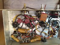
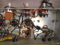
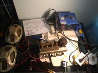
Can't scan it - here are cellphone pics of amp and power supply:
Can't scan it - here are cellphone pics of amp and power supply:
Attachments

Last edited:
Jim McShane's price for the F&T part is close to the Amazon price and he has the clamp you need. Factor in shipping costs for 2 parcels vs. 1 and buying from Jim seems sensible to me.
Remember, the 20% tolerance of those old capacitors. 8% is the difference between 0.25 μF. and 0.27 μF. That's nothing to get excited over.
Hi Eli
On a somewhat unrelated note, do you know if Magnavox 9302-10 also uses the F&T cap ? If so I can order two from Jim McShane. My 9302-10 is in mail at present - so I can't look at it and take pictures. That will be my next project if I don't hurt myself with this one
Thanks
Holy cow - are my eyes playing tricks on me, or are the coupling caps between stages actually in those ceramic networks? If so, it's the first time I've ever encountered that. Even more reason to remove them and replace with discrete components. Thanks to Tom for the excellent sleuthing!
The .05 (C5, C9) is "bass boost" - use the dotted resistor instead. The .25 (C4, C8) is treble boost - just delete it. This amp shows separate R/L Volume and small output transformers (portable phono version). Yours may have loudness compensation (bass boost at lower volume) You can leave that or remove the ceramic module.
Can't scan it - here are cellphone pics of amp and power supply:
When you say "leave it or remove tje ceramic module" , you are referring to K1 and K2 in the first image right!
Hi everyone
Finally got to the project! This last couple of days, I made a lamp limiter and started rewiring. I have a couple of questions. If you look at the first image, near the audio output section, I can see the output going via R9 [5600ohm] and C5 [0.05mfd] [please look at the schematic image]. However there is a 56kohm resistor that is also going straight to the output. This is where the schematic shows I can bypass the R9/C5 and use a 27k resistor. As you can see there is one of 56k there already. Then I can just remove the R9 and C5 and leave the 56k there - or should I remove the 56k and replace with 27k. I guess I can try both.
Another question is re: power supply. If you look at the second image, on the bottom right, I have the power coming in via two brown leads going to the post. However if you look on the top of the post, two black wires leave, I am thinking the primary winding of the power transformer. The power lead coming in on the far right does not seem to go to the transformer winding. There is another set of red/green/black that seems to take the power out and return, ending via green on the transformer winding. Does that mean the phono that was supplied by it was in series?
If so I can feed the posts with the two transformer black leads right? I did check for the continuity using ohms on the multimeter and the two black wires have continuity.
Thanks all
Attachments
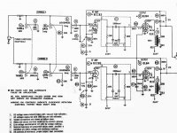
R9, 15 are the feedback resistors, and control the overall gain. With lower values, distortion and frequency response improve. Go too low and it may oscillate, but you can try different values. The .05 and .25 caps introduce a deliberate tilt in frequency response, compensating for what was in the console, none of which you're using.
Two coupling networks shown on schematic - I only see one. Possible it has six leads, combining both? Replace with discrete parts: 240K or 220K resistors, .01 caps, 470K resistors. (the 250 pF caps will roll off high frequencies a little - skip them) But for now, leave it - do the minimum to get it working first.
Black wires are power transformer primary. Was switched on / off through the record changer.
replace the large power caps with new. You may be able to dismantle the old can and put them inside with wire leads to connect to the chassis. The tone controls work by loading the ceramic cart. these will be useless with a modern input unless you drive the input with a 47pf cap in parallel with a 2.2m resistor. these values are a guesstimate of a ceramic cartridge. If the tone controls are lost, use the 500k treble pot for the volume. at least 1 of the 250pf caps driving the output tube could be removed.
Hi all
Finally I got to it and managed to make it play. As you can see from the image the old can capacitor is still there. I am waiting on the order of the 50mfd dual capacitors. I reused the speakers it was driving - they are rotten as you can see but didn't want to risk good ones!
I used the preamp tube pins 2 and 7 for the grids, fed them from an old mp3 player uvia 100kohm pots and 100ohm resistor. Powered through a lamp limiter. I am super chuffed, this is my first valve project. It was fairly clean without any overt hum.
Now I am going to go and disconnect the left two pots on the chassis, place the new ones in there and make proper speaker posts. Then the case/box!
I will probably have a whole bunch of questions in the future.
Thanks everyone for all the help here.
Attachments
Hi all
I think I broke it now ! I removed the 0.25 caps and took it to ground. That is c4 and c8 on the schematic form two posts above. Removed the 0.05 and left the 56k resistor the send the audio signal to the output. I connected the power/ground. It played well for a few minutes. Suddenly started to produce buzzing sound, then made a pop and sound stopped altogether. I can still see the filaments on the output tubes glowing. Under the tubes, nothing looks burnt at least on the surface. I was driving it via lamp limiter and I did not see any bright lights Also the big can capacitor has around 12v ac between three if it's leads and the ground.
Any ideas where should I start looking?
Thanks
I think I broke it now ! I removed the 0.25 caps and took it to ground. That is c4 and c8 on the schematic form two posts above. Removed the 0.05 and left the 56k resistor the send the audio signal to the output. I connected the power/ground. It played well for a few minutes. Suddenly started to produce buzzing sound, then made a pop and sound stopped altogether. I can still see the filaments on the output tubes glowing. Under the tubes, nothing looks burnt at least on the surface. I was driving it via lamp limiter and I did not see any bright lights
Also the big can capacitor has around 12v ac between three if it's leads and the ground. Any ideas where should I start looking?
Thanks
- Status
- This old topic is closed. If you want to reopen this topic, contact a moderator using the "Report Post" button.
- Home
- Amplifiers
- Tubes / Valves
- Looking for guidance to bring an amp back to life