Troubleshooting inquiry.
Does anyone have experience with this circuit from EBAY? I was able to get the pcb and all associated parts assembled but only one channel functions.
Went through all component checks many times over and unable to find any mistakes.
Without tubes in socket to simulate open circuit for B+, I get full B+ for both tubes, but once the tubes go in, one channel appears to be dropping B+ by more than half only on the bad side, not the functioning side. Evident by seeing only half of the dual triode filament lighting.
HV (250Vdc) does not appear to be current limiting since the full B+ is available at the source. Traced all connections but unable to find any problems. Tried two sets of 12AX7's and 12AU7's still only half functions of the dual triode functions.
Heater voltage (series 12.6Vdc; #9 tap is grounded on pcb) was checked as well on the pins of the tubes but still only half of the triode works. Strange.
Wondering does this design ever worked. Anyone have any suggestion as what may be causing the half triode problem?
Attachments
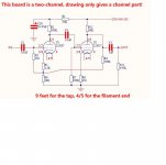
Sounds like one side of the 12.6V supply is grounded, shorting out one side if the heater. If pin9 is grounded then one side should be +6V and the other -6V.
Steveu, thank you for your pointer which lead me to figure out why.
The heater supply is derived from a switch mode HV module that supplies the B+. Little do I know, the grounds of both HV and heater are the same ground. This was actually causing part of the filament going to ground as you surmised.
What gave it away was your pointer on measuring #9 to #4 & #5. It was not measuring +6 but rather -11 or so on 4 and I forget what was on 5 referenced to #9 or gnd.
I kept the HV but used a linear 317 from a local +18V supply down to +12.6V floating. And that did it. Tubes now lights! And buffer works with what appears to have around 16 dB of gain (300mV input / 2V output).
Thanks again!
Are you sure it's series? The two tubes use different currents. Usually, if pin 9 in grounded, pin 4 and 5 are shorted and you run it from 6V...
Thanks for chiming in, Kodabmx. It's in series confirmed, but my heater supply was part of the HV switch-mode module that has both gnd linked.
Steveu pointed me in the right direction and used a separate linear supply floating on the heater. All good at this point.
Thanks!
Are you sure it's series? The two tubes use different currents. Usually, if pin 9 in grounded, pin 4 and 5 are shorted and you run it from 6V...
The more I think about this which shows how little I know about tube circuitry, your reply just gave me the idea of running the heaters in parallel.
To utilize the HV module built in heater supply, I'll tie #4 & #5 and run the heater at 6.3V via gnd. The heaters of both tubes when on in series configuration draws approx. 375mA. Most likely the parallel configuration will be double to less than 800mA which the supply will handle with ease (spec at 3A).
Thanks Kodabmx!
- Status
- This old topic is closed. If you want to reopen this topic, contact a moderator using the "Report Post" button.
- Home
- Amplifiers
- Tubes / Valves
- Troubleshooting 12AX7-12AU7 buffer from EBAY