I take it then that my hand marking is correct? bringing it in after the C3 and then just finding the place for 39pF filtering to add.
On the subject of which resistors may have been at risk when V19 threw fireworks: R34 and the bias pot may also have to be checked?
FYI today I am ordering a matched pair of Sovtek 6550WE for screen regulators and will be moving the original ones to OP V15/V19 after checking the suspect resistors.
On the subject of which resistors may have been at risk when V19 threw fireworks: R34 and the bias pot may also have to be checked?
FYI today I am ordering a matched pair of Sovtek 6550WE for screen regulators and will be moving the original ones to OP V15/V19 after checking the suspect resistors.
I take it then that my hand marking is correct? bringing it in after the C3 and then just finding the place for 39pF filtering to add.
On the subject of which resistors may have been at risk when V19 threw fireworks: R34 and the bias pot may also have to be checked?
Foe balanced inputs, if you want an input filter, you need an RC filter on each of the input lines
(both pins 2 and 3) to balance the impedances.
You can check R34 along with the rest. Personally I would check all of the resistors and diodes
while the amplifier is opened up.
The input coupling capacitor C3 is best removed. If you want to keep it in the balanced version,
you need one for each line (both pins 2 and 3).
Last edited:
Faux balanced inputs, if you want an input filter, № 1 - you need an RC filter on each of the input lines (both pins 2 and 3) to balance the impedances.
№ 2 - You can check R34 along with the rest. Personally I would check all of the resistors and diodes while the amplifier is opened up.
№ 3 - The input coupling capacitor C₃ is best removed. If you want to keep it in the balanced version, you need one for each line (both pins 2 and 3).
№ 1 - I agree with.
№ 2 - R34? Look as I might at the schematic, no R34.
№ 3 - C3 removal…
Reading a prior comment, wherein you regard C3 as a high capacitive load on the source, I beg to differ:
First, the 10 kΩ resistor from RCA input to pot limits whatever impedance load to just that.
Second, the 'knee' in the F=1/(2πZC) relationship is 1/(6.28 × (470,000 || 301,000) × 0.47×10⁻⁶) → 1.5 Hz. That's with the pot wide open.
Third, the right-hand-side of the 0.47 µF isn't connected to ground, effectively or physically, sooo … the idea of it being a significant capacitive load kind of vanishes, you know?
Anyway… just a spurious comment, I suppose.
Just saying,
GoatGuy ✓
resistors may have been at risk when V19 threw fireworks: R34 and the bias pot may also have to be checked?......R34? Look as I might at the schematic, no R34.
First place I looked, the grid to bias supply resistor on V19.
I would fire this amp up with no output tubes installed and verify that the plate, screen and bias voltages are somewhat close to what's expected. Yes the voltages will be a bit too high, so I would use a Variac set to somewhere around 100 volts if one is available.
I was experimenting with a DIY amp that makes 75 watts per channel from pairs of 6550's when there was a white flash and a blown 6550. The plate supply had died (I knocked the plug out) while the screen grid remained powered. The poor grid attempted to eat all of the plate current, and was vaporized.
Reading a prior comment, wherein you regard C3 as a high capacitive load on the source, I beg to differ: First, the 10 kΩ resistor from RCA input to pot limits whatever impedance load to just that.
We're not talking about using the RCA jack input, but rather adding an XLR connector.
If he leaves C3 installed when going balanced (taking the positive input phase to R12),
then C3 will hang off the positive phase directly to ground when the (unused) pot is at minimum.
Not good. Also C3 degrades the sound so badly that it should be removed, regardless.
I've removed C3 for several D-150 owners and all were very happy with the results.
Last edited:
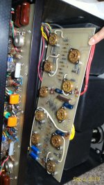
opened up the amp and got the pcb in the middle exposed. measured everything. 10 Ohm/3W dale resistors by V19 and V15 were done in. Will order replacements this week. The bias pots seem to check out too, phew. The screen regulator tubes are in the mail ") . So hopefully in a week I can get the amp back in shape
. So hopefully in a week I can get the amp back in shape  .
.
p.s. re: balanced input : I see now the symmetry R7/R8 so I got your point re: keeping R7 in the circuit. Will have to check the board layout and how best to do that. Thx.
. So hopefully in a week I can get the amp back in shape .p.s. re: balanced input : I see now the symmetry R7/R8 so I got your point re: keeping R7 in the circuit. Will have to check the board layout and how best to do that. Thx.
Attachments
Last edited:
You want the input grids to always have a ground reference, whether or not there is an input connected.
That's what the two 470k resistors do. The pcbs are very delicate, use extreme caution when desoldering.
Check all the rest of the resistors on the board while you can, because it's easy to do right now.
Also clean the pots with good contact cleaner now.
That's what the two 470k resistors do. The pcbs are very delicate, use extreme caution when desoldering.
Check all the rest of the resistors on the board while you can, because it's easy to do right now.
Also clean the pots with good contact cleaner now.
Last edited:
I received a pair of Sovtek 6550WEs from Jim (who was recommended earlier in the thread). However these are only loosely matched compared to the original AR 6550As. They will probably be good enough for the grid regulator. However this puts a new light on how valuable the original tubes are, which based on hand written values on the stickers have been matched to 2 digits? AR must have had a large stock from the same batch to come up with such close matches.
So now I am thinking of the safest way to bring those online. My friend is suggesting that I run them first with plate and screen fuses removed for 24 hrs to allow for some degassing (since these tubes probably sat unused for a very long time). Then use a variac to slowly bring the anode voltage up allowing for some heat up time, but doing a pair at a time may take a long time to complete? Any thoughts on what a reasonable course of action might be?
So now I am thinking of the safest way to bring those online
. My friend is suggesting that I run them first with plate and screen fuses removed for 24 hrs to allow for some degassing (since these tubes probably sat unused for a very long time). Then use a variac to slowly bring the anode voltage up allowing for some heat up time, but doing a pair at a time may take a long time to complete? Any thoughts on what a reasonable course of action might be?
Last edited:
Depends on how long the tubes have sat. With WWII surplus tubes, I like to run just the filament (no grid, screen or plate voltage) for 24 hours to clean up the vacuum- helps keep them from arcing. I might be tempted to create a jig to do this though, as some amps really don't like running without load on the B+. These tubes probably haven't really sat for that long, so 24 hours is probably excessive.
That said, it sounds like you already had one of the original tubes arc, so maybe they are a little gassy and a bit more burn-in time wouldn't hurt.
That said, it sounds like you already had one of the original tubes arc, so maybe they are a little gassy and a bit more burn-in time wouldn't hurt.
last update: reassembled the amp with no OP tubes. applied power. the mains measured 126V on the front dial. measured voltage at pin 5 of V21/V22 grid Vregulator sockets and got 345V (350V called out on the schematic). So the 7 zeners checked out. then plugged in two newly purchased Sovteks into V21/V22 and measured voltage at pin 4 of all OP tube sockets and got 374.5V (nominal 360V on the schematic).
p.s. just by looking over the smaller tubes on the back plate, all had some glow in them except for the four 12AX7s in the middle. not sure of their intended function but I guess that was normal without the OP tubes biased for work?
so I guess the amp is ready for plugging in the original 8 GE6550As. I will remove the plate and screen fuses and run only the heater on them for some hours. And then we see about the next step of getting the anode voltage up there.
p.s. another thing which i noticed last time and it bothered me: when the clamps are applied to the tube bases they tend to pull on the tube and pull the pins out on the opposite side. Not sure how to get around that unless I just plug them in and let the clamps hang loose?
finally ran the tubes at the 120V PS setting but with all bias trimmers turned all the way down. Nothing sparked. However when I switched the knob to look at individual tube bias current the front indicator showed nothing. (in the manual it says the trimmer are capable of settings between 25mA and 85mA which puts the recommended 55mA in the middle. So I expected the hand on the dial to start showing something immediately. I turned the trimmers up (clockwise) about a 1/4 turn and still no indicator movement.
@Rayma: do you think the dial circuit might be faulty? or it takes turning trimmers more before they come alive? I am afraid of turning them up and overbiasing if something is wrong by any chance.
p.s. another thing that bugs me is that at approximately the same trimmer setting some tubes feel like they are running hotter than others (just by feeling the envelope with hand). Thx.
do you think the dial circuit might be faulty? or it takes turning trimmers more before they come alive? I am afraid of turning them up and overbiasing if something is wrong by any chance.
Check the voltage directly across the 1R 3W current monitor resistors.
This should vary with the pot setting, nominal 50 or 60mVDC each.
Unless the pot is turned up enough, there will be little or no reading, but be careful.
forgot to post the last update: it turned out that the front knobs (5 pole switches) for pointing dials to each tube for bias adjust were (still are) an issue.
After rotating them back and forth like crazy I got the left one to work reasonably well i.e. measure repeatably and I set the bias on those tubes. the right dial only works in one position though. in the two middle positions when I jiggle the shaft (there is some plunge free play) I can get the hand on the dial to jump up and measure something, but in the end left position (no free play) the dial just sits at the bottom. I ordered DeoxIT on amazon and will try that next but I am not so sure that it will fix it. AR should have really used gold plated contacts for this price range amp.
After rotating them back and forth like crazy I got the left one to work reasonably well i.e. measure repeatably and I set the bias on those tubes. the right dial only works in one position though. in the two middle positions when I jiggle the shaft (there is some plunge free play) I can get the hand on the dial to jump up and measure something, but in the end left position (no free play) the dial just sits at the bottom. I ordered DeoxIT on amazon and will try that next but I am not so sure that it will fix it. AR should have really used gold plated contacts for this price range amp
.I ordered DeoxIT on amazon and will try that next but I am not so sure that it will fix it.
AR should have really used gold plated contacts for this price range amp
Gold contacts would not be suitable for a power switch like these. This amplifier is 43 years old, and would
be expected to require service for proper function. Do not operate the amplifier further until the contacts
are properly cleaned. Do not rely on only moving the switch to clean the contacts. Follow Caig's instructions carefully, and do not spray any other part of the amplifier than the switch contacts. Do not spray into the tube sockets, or near the pc boards.
Last edited:
Ok. I will take a closer look. I believe the switches are mounted on pcbs behind the front panel which I was hoping not to have to take apart. so I was thinking of just sticking the straw in (I could see little openings on the switch body) and just spraying in. It is also pretty dusty there and hard to reach. maybe I use some compressed air first.
It is also pretty dusty there and hard to reach. maybe I use some compressed air first.
No compressed air, it would make things worse, only vacuum if available.
- Status
- This old topic is closed. If you want to reopen this topic, contact a moderator using the "Report Post" button.
- Home
- Amplifiers
- Tubes / Valves
- D150 monster amp and funny tooobz