Scott remarked about the apparent great condition of the tubes in an amp picture before. Only after that did I wipe the dust off of them to have a closer look: well I am no expert but I could not see any sign of use inside the glass. So hardly used if at all  .
.
I almost wish they had been used some since I know from a friend of mine who is into ham radio that they prefer to rotate their spare tubes in their amplifiers to degass any oxidation from atmosphere leaking in. Anyways here is a photo of 4 of the tubes:
.I almost wish they had been used some since I know from a friend of mine who is into ham radio that they prefer to rotate their spare tubes in their amplifiers to degass any oxidation from atmosphere leaking in. Anyways here is a photo of 4 of the tubes:
Attachments
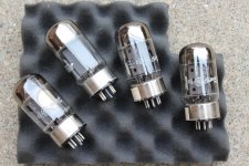
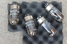
I could not see any sign of use inside the glass.
It's hard to tell their function from appearance, but make sure they go back into
the correct sockets. Clean their pins with alcohol while they're out.
give me few days to wrap my head around funny schm , and I'll comment whatever I can
recupperating from stuborn and boring childish flu , so head is not mine , even more than usual
cunning plan is to test da tubes , either in situ or in someone's toob tester
we'll see
videla zaba da se konji potkivaju , pa i ona digla nogu
sta joj je to trebalo .......
prevedi , ako si majstor
recupperating from stuborn and boring childish flu , so head is not mine , even more than usual
cunning plan is to test da tubes , either in situ or in someone's toob tester
we'll see
videla zaba da se konji potkivaju , pa i ona digla nogu
sta joj je to trebalo .......
prevedi , ako si majstor
both the tubes and the sockets are numbered so they will go back as originally installed .
as for having the tubes tested: I have to put some thought into it. I do not feel like mailing the glassware around and I am not sure what may be available locally.
@Zen: nema zurbe (no hurry) and you take care of your flu
.as for having the tubes tested: I have to put some thought into it. I do not feel like mailing the glassware around and I am not sure what may be available locally.
@Zen: nema zurbe (no hurry) and you take care of your flu
I can't remember that I posted something , then deleted it ..... , though - who knows several days ago .... submit and cancel were so similar buttons
I know that somewhere I wrote something about their construction team using bad weed , but can't remember where
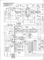
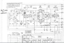
frankly , I didn't invest too much time in deciphering it , so putting it here , for hopeful brainstorm ..... why , on earth , they needed these two triode systems , most left , right bellow RCA input symbol , dangling on neg. input LTP side ?
schm taken from on-line ARC Database
I know that somewhere I wrote something about their construction team using bad weed , but can't remember where
frankly , I didn't invest too much time in deciphering it , so putting it here , for hopeful brainstorm ..... why , on earth , they needed these two triode systems , most left , right bellow RCA input symbol , dangling on neg. input LTP side ?
schm taken from on-line ARC Database
Attachments
Iwhy , on earth , they needed these two triode systems , most left , right bellow
RCA input symbol , dangling on neg. input LTP side ?
That's the unity gain phase inverter. The entire D150 amplifier circuit is balanced,
but the input is single ended.
@rayma
Could you please mark on the page(s) where you thought I should bring +/-/gnd from an XLR input? and cross out what would need to be disconnected. I will (most probably) try the amp with unbalanced inputs first, to make sure it works as originally intended. But later the intent would be to drive it with a balanced source (an Aleph P preamp with a 1kOhm attenuator at its output). Thx a lot.
Could you please mark on the page(s) where you thought I should bring +/-/gnd from an XLR input? and cross out what would need to be disconnected. I will (most probably) try the amp with unbalanced inputs first, to make sure it works as originally intended. But later the intent would be to drive it with a balanced source (an Aleph P preamp with a 1kOhm attenuator at its output). Thx a lot.
@rayma
Could you please mark on the page(s) where you thought I should
bring +/-/gnd from an XLR input?
To convert the D150 to balanced operation:
Remove V1 and V2
Remove R5, R6, C1, C3, and J8
Connect positive balanced input line to left end of R12
Connect negative balanced input line to left end of R15
The input impedance is now 470k per phase.

That's the unity gain phase inverter. The entire D150 amplifier circuit is balanced,
but the input is single ended.
yup , messy head , not seeing obvious
my mistake , searching for reason ...... instead - they could route NFB to grids instead , slightly sacrificing some Rin
so , tnx to rayma , puzzle solved and recipe given
for those wondering what keeps me busy and away from D-150 refurb for the moment: I am still making a 6-channel preamp for my other setup which can be seen here:
https://www.diyaudio.com/forums/multi-way/123512-ultimate-baffle-gallery-260.html#post5670164
https://www.diyaudio.com/forums/multi-way/123512-ultimate-baffle-gallery-260.html#post5670164
instead - they could route NFB to grids instead , slightly sacrificing some Rin
All the ARC tube power amplifiers of that era used the same balanced cross-coupled
driver circuit with the phase inverter at the input, as well as similar board layouts
and parts, for the D51, D75, D76, and D150 amplifiers.
Even the Electronic Industries D50 and D100 were very similar, but with a different layout
and Dynaco transformers.
Last edited:
finally getting around to look at the monster again. in parallel with my LX521 speaker work.
first checked PS voltage, going up to 525V before the rectifier. But I overlooked that the original PS board (PWB 108) used a metal standoff to connect negative to chassis, so there was no bias current since I had no wire connection from my bus to chassis.
once that was fixed, turned on power, tubes heating up and a glass crack sound and a flash from the OP tubes and turned it off quickly. My friend who was helping me could not tell from which tube exactly it came and on casual looking all still looked fine. Turned it back on and V19 threw fireworks and blew line fuses (which is both strange and worrisome since the plate and the screen fuses did not). the glass on that tube actually separated from the base. the rest looked fine.
>> So I could use some expert advice on having the tubes changed. what is the most sensible approach? I was thinking, if two of those big tubes (V12 & V21) are used as rectifiers but are still matched (I need to take them out to see if they have written values on them like the rest), then use those as OP in V15 & V19 and purchase another pair.
I think I saw Sovtek and Tung Sol 6550 online. Neither is regarded as well as the original ones were. Someone here mentioned changing for a different (KT88) tube altogether for OP but I am not sure what such a change would entail as it would stray away from the original. I am still trying to just prove the circuit and then will go on and change it to balanced input.
So next steps: get some tubes, change line fuses, plug only rectifier tubes and check voltage on OP sockets and then plug in all OP tubes. Does that sound reasonable?
Thanks.
first checked PS voltage, going up to 525V before the rectifier. But I overlooked that the original PS board (PWB 108) used a metal standoff to connect negative to chassis, so there was no bias current since I had no wire connection from my bus to chassis.
once that was fixed, turned on power, tubes heating up and a glass crack sound and a flash from the OP tubes and turned it off quickly. My friend who was helping me could not tell from which tube exactly it came and on casual looking all still looked fine. Turned it back on and V19 threw fireworks and blew line fuses (which is both strange and worrisome since the plate and the screen fuses did not
). the glass on that tube actually separated from the base. the rest looked fine.>> So I could use some expert advice on having the tubes changed. what is the most sensible approach? I was thinking, if two of those big tubes (V12 & V21) are used as rectifiers but are still matched (I need to take them out to see if they have written values on them like the rest), then use those as OP in V15 & V19 and purchase another pair.
I think I saw Sovtek and Tung Sol 6550 online. Neither is regarded as well as the original ones were. Someone here mentioned changing for a different (KT88) tube altogether for OP but I am not sure what such a change would entail as it would stray away from the original. I am still trying to just prove the circuit and then will go on and change it to balanced input.
So next steps: get some tubes, change line fuses, plug only rectifier tubes and check voltage on OP sockets and then plug in all OP tubes. Does that sound reasonable?
Thanks.
Last edited:
There are no rectifier tubes, just the silicon diode module BR1. Two of the large tubes however are (in parallel) screen regulators, V21 and V22.
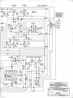
If V19 failed, be sure to also check the related V19 resistors R47, R49, and R51. Be sure to turn down all 8 bias pots to a low setting before turning the amplifier on. See the D-150 schematic in post #5.
It's also useful to use the 220VAC line voltage setting on the power switch for warming up the amplifier, before switching it to 120VAC.
Thanks Rayma. All good suggestions. Will do as soon as I found replacement tubes. (and you got me: I meant V21/22. sorry for the misnomer).
p.s. I hope those resistors are on the back and accessible else.. arghhh
p.s. I turned all 8 bias trim settings all the way counterclockwise (after the tube blew up) but none was very far from it though so taht was not it. there must have been something wrong with that tube. I suspect they were not used and maybe some atmosphere leaked in.
Last edited:
frankly , I didn't invest too much time in deciphering it , so putting it here , for hopeful brainstorm ..... why , on earth , they needed these two triode systems , most left , right bellow RCA input symbol , dangling on neg. input LTP side ?
"Anode follower", or "unity gain inverting amplifier". Kind of phase-splitter.
I got that from Rayma before. The balanced input will be implemented as per the markings here. For filter cap change 390pF to 39pF I just have to find where to mount the small cap since currently it is mounted on the pot which I do not see the purpose in keeping in the signal flow.
Else, I will not be adding any connectors to the housing as the goal is to preserve everything so it can be brought back to the original state (in case I am selling the amp after a while). I will just lift one side of those 10k resistors and solder wires to a pig tail XLR which I will ziptie to the housing, and lift that 301k resistor and that's it.
Right now I have a bigger problem with those resistors which need to be checked not being accessible. I expect they will be right by the tube base and the whole amp has to come apart to get to those. I cannot describe to you how difficult that amp layout is to service anything that is not on the rear panel.
Attachments
Last edited:
- Status
- This old topic is closed. If you want to reopen this topic, contact a moderator using the "Report Post" button.
- Home
- Amplifiers
- Tubes / Valves
- D150 monster amp and funny tooobz