Hey everyone. I thought I'd share a recent rebuild I did.
I took apart the second amp I ever built, and said to myself "This is horrible! Do it again!". So here we are.
I gutted everything down to the chassis and the coils, and started to build it again.
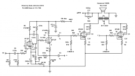
My design goals this time were to make a triode connected class A amp that was good for at least 20W. This one does 25W, and according to the PPcalc simulation, the distortion is under 0.01% for the output stage, and the damping factor is 10.9!
The other goal was not to use any solid state parts at all to see what it would sound like without a modern stiff power supply. Win all around!
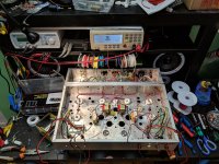
I used the Hammond 278CX into a pair of 6D22S into a Hammond 193Q 10H 500ma choke with a DCR of 53R, but I wanted more voltage for the first stage. So I used a pair of 6Z4P diodes for a cap input filter good for 460V. I also used a tube diode for the bias supply (6CA4). All these parts were in the stock or junkbox so why not, right?
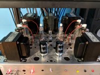
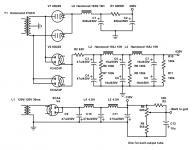
Here are some pictures and the schematics. This is a really kick butt amplifier if I do say so myself.
I took apart the second amp I ever built, and said to myself "This is horrible! Do it again!". So here we are.
I gutted everything down to the chassis and the coils, and started to build it again.
My design goals this time were to make a triode connected class A amp that was good for at least 20W. This one does 25W, and according to the PPcalc simulation, the distortion is under 0.01% for the output stage, and the damping factor is 10.9!
The other goal was not to use any solid state parts at all to see what it would sound like without a modern stiff power supply. Win all around!
I used the Hammond 278CX into a pair of 6D22S into a Hammond 193Q 10H 500ma choke with a DCR of 53R, but I wanted more voltage for the first stage. So I used a pair of 6Z4P diodes for a cap input filter good for 460V. I also used a tube diode for the bias supply (6CA4). All these parts were in the stock or junkbox so why not, right?
Here are some pictures and the schematics. This is a really kick butt amplifier if I do say so myself.
Attachments

Last edited:
Agreed, equalisation bleeders would be a nice touch.
It weighs almost 30kg!
Thanks for the comments.
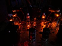
I don't know if it's visible on the picture, but I have neons on the front to show at a glance if there is power to a stage. Because of the slow warm up of the 6D22S and 6P45S, the bias is there before they get hot")
Also not in the drawing, the heater supplies. The 6P45S tubes run from a Hammond 167V12, the diodes run from the 278CX, and the 6F12P get power from the 12V filament winding on the bias transformer. It's a Hammond but I can't remember the model. It was surplus from the 60s I think. 120V@30ma, 12V@450ma though. I've had it for years just waiting for a use for it!
Surprisingly, the 6Z4P tubes make HV in about 6 seconds.
When I first chose this iron, it was for my first higher power build, but I didn't have the knowledge and skill I have now. It was 8 6P3S tubes and switchable from triode/regulated tetrode/ or UL. Then it became KT88 and UL only, and now this. I like it enough that I might rebuild it on a new chassis. The thing looks like Swiss cheese!
It weighs almost 30kg!
Thanks for the comments.
I don't know if it's visible on the picture, but I have neons on the front to show at a glance if there is power to a stage. Because of the slow warm up of the 6D22S and 6P45S, the bias is there before they get hot
Also not in the drawing, the heater supplies. The 6P45S tubes run from a Hammond 167V12, the diodes run from the 278CX, and the 6F12P get power from the 12V filament winding on the bias transformer. It's a Hammond but I can't remember the model. It was surplus from the 60s I think. 120V@30ma, 12V@450ma though. I've had it for years just waiting for a use for it!
Surprisingly, the 6Z4P tubes make HV in about 6 seconds.
When I first chose this iron, it was for my first higher power build, but I didn't have the knowledge and skill I have now. It was 8 6P3S tubes and switchable from triode/regulated tetrode/ or UL. Then it became KT88 and UL only, and now this. I like it enough that I might rebuild it on a new chassis. The thing looks like Swiss cheese!
Last edited:
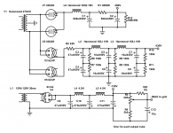
Ok so I added those sharing resistors across the series connected caps, and adjusted the 15k resistor in the VA/PI down to 3k3. Now it's got 390V instead of 330V...
Measured it with a watt meter, this amplifier takes 333W from the wall and has a power factor of 0.92!
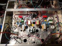
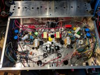
I adjusted the schematics, and added a pic of the finished amp wiring.
Perhaps a MOD could update the OP with the new graphics?
Thanks!
Measured it with a watt meter, this amplifier takes 333W from the wall and has a power factor of 0.92!
I adjusted the schematics, and added a pic of the finished amp wiring.
Perhaps a MOD could update the OP with the new graphics?
Thanks!
Attachments

Last edited:
kodabmx,
The junction of R6 and R7 should be connected to the junction of C3 and C4.
Repeat that pattern for R8 and R9, C5 and C6;
and R10 and R11, C7 and C8.
That will do a reasonable job of dividing the DC voltage across the capacitor pairs, even if they have different leakage currents.
You also should have a bleeder cap across C2, and either increase R1 to 10 Watts, or also put a bleeder across C1.
If you forget to put the output tubes in when you test, then when you turn the power off, C1 and C2 will eventually discharge.
Safety First.
yes, aside from discharging caps on power down, the whole point of the equalising resistors is to ensure equal voltage across the series caps, without those resistors, the voltage across those series caps may not be the same and the voltage across one cap can easily be exceed to cause that cap to fail....i am sure that was a typo on the drawing...
Perhaps a MOD could update the OP with the new graphics?
you can do that yourself to your own thread, let me know if you have problem editing...
but if it were up to me, i will leave the first post as it is so reader can track the history of changes....up to you....

I will add a 100K resistor from 290V to ground. I find one resistor will bleed all of the power. With the tubes in, there is no need, also the neon bulb will drain it down to about 70V. As far as R1 the Pd is only <2W, a 5W part is fine, isn't it?
As a matter of safety, I treat every amp as if the caps are full. The first thing I do when working on it is clip a 2k resistor from B+ to ground and leave it there until I'm finished.
Yes, the caps and resistors are tied together (otherwise it wouldn't do anything but waste power), I simply forgot it on the schematic.
Thanks for catching the error, guys.
Attachments
Last edited:
you can do that yourself to your own thread, let me know if you have problem editing...
but if it were up to me, i will leave the first post as it is so reader can track the history of changes....up to you....
Nope. It will let me edit the text, but not manage the attachments. I like the idea of leaving the schematics in the OP alone, but I'd like to add the wiring pic.
Nope. It will let me edit the text, but not manage the attachments. I like the idea of leaving the schematics in the OP alone, but I'd like to add the wiring pic.
ok ...done...
What do you all think of this amp but connected UL? I was thinking of rigging a switch for it and I think the current operating points should work, but I wanted to see what you thought about it...
Thanks.
i am iffy with the switch idea, if you do not need all that power, a triode mode is better...
if you want to go pentode, then regulate the G2 and G1 supplies...
What do you all think of this amp but connected UL? I was thinking of rigging a switch for it and I think the current operating points should work, but I wanted to see what you thought about it...
Thanks.
UL is too wishy-washy for me. Go triode or pentode with a regulated G2, and ideally regulated bias supply.
I'm not a fan of switches for these modes unless the bias is adjusted to suit, like Anatoliy says.
- Status
- This old topic is closed. If you want to reopen this topic, contact a moderator using the "Report Post" button.
- Home
- Amplifiers
- Tubes / Valves
- New rebuild - 6F12P-6P45S Triode