I am a bit surprised that there shall be a new way of using a triode...when reading this claims:
http://aries-cerat.eu/products/preamplifiers/impera-ii-ref
"...…prepare to be surprised.
A new way of using triodes is born,in fact you can say it is a whole new active component .A component that gives the new Impera preamplifier extra-ordinary performance,unrivalled by any tube or transistor preamplifier stage."
more details:
"Inside an Inverted Triode tube, the electron stream emitted from a heated cathode, is accelerated towards the anode, now a wire-grid-like structure . The electron flow is now unimpeded since no grid structure exists between the anode and cathode.
Instead, a plate-like structure, enveloping the cathode/anode assembly, called the control “grid” is shadowing the anode electrical field, having a very high negative electrical field itself, thus “pushing” the electrons away from the anode.
This mode of electron flow control is completely different than a triode mode of operation.
The parameters of this new active element, are far different than any conventional triode; the inverted triode actually acts like a virtual “vacuum state transformer”. Instead of having gain, the inverted triode has a gain that of a fraction of unity,just like a step down transformer. The internal resistance is many times lower, and input capacitance is nearly zero.
The extra-ordinary parameters of the inverted triode used (100 times lower plate resistance than a 6SN7 tube, zero input capacitance) ,gives the output stage unrivalled measured performance : 2Hz-500KHz bandwidth , figures unreached by any triode - transformer output stage."
...and more:
"An example of the Inverted Triode’s technical advantage over a typical vacuum tube,ex 300B,is a comparison of the two ,driving the same output transformer.The Inverted Triode tube presented a power bandwidth of 2Hz-500.000Hz where the 300B tube had a bandwidth of 15Hz-100.000Hz. Same transformer, same driver tube, but 5 times the bandwidth for the Inverted Triode tube."
...ok, normally I would say marketing blabla, but the technical data given seems to be too serious and the manufacturer has for sure a lot of good ingedients in his stuff...
I guess this concept is not new, as not too much is new under the tubes sun, can you lead me to some information explaining this further ?
Last edited:
I guess this concept is not new, as not too much is new under the tubes sun, can you
lead me to some information explaining this further ?
https://lib.dr.iastate.edu/cgi/view...e.com/&httpsredir=1&article=14297&context=rtd
I remember reading about it in one of the Terman books. Also Steve Bench had a design on his website for an inverted triode power amp. Forum member Smoking-amp has also suggested it as a way of applying feedback (I hope he's ok; he hasn't appeared here since the Carolina hurricane).
Also Steve Bench had a design on his website for an inverted triode power amp.
I built it. The concept is sound and works quite well with low Mu tubes. It however does NOT amplify voltage, in fact the drive voltage is Mu times higher than the output voltage. A tube like a 6AS7 (Mu = 2) needs 100 volts of drive for 50 volts of output. The grid is used for the "plate" and can easily be over dissipated if trying to make big power. I melted a few 6080's finding this out. It may be useful for a preamp or headphone amp.
Inverted Tube Operation
Inverted Triodes - The 6AS7/6080 Family
Inverted Triode Single Ended Output Transformerless Test Amplifier
"Inverted" mode is very old as an Electrometer input. It gives high input resistance and a voltage *loss* which is frequently acceptable. The ex-Plate is much more rugged than the grid of any comparable tube.
As said, to "exploit" the high conductance as a Power amplifier just puts too much power in the fragile grid.
As a preamp, it can work, and can lead to exciting ad-copy. However zero input capacitance is untrue so many ways (and not that important if it were).
Thanks for the Richardson paper. Much meat there.
Last edited:
Steve Bench and his designs and Roger Modjeski
Steve actually has allot of very interesting stuff and his site is very informative ,besides that he let me use one of his power supplies in a preamp I was going to put on the market,without asking for a thing! If anyone does hear from him or contact him please tell me,also does anyone know how Roger Modjeski is another great guy and friend I cannot get in touch with?
Thanks y’all
Hello.
Mr. Modjeski presented an interesting talk on vacuum tubes at the recent 2018 Burning Amp Festival. Please see the thread in the Pass Labs Forum which is entitled Burning Amp 2018 Updates Thread ; posts #91 and #92. Most probably Mr. Nelson Pass [nelson@passlabs.com] and/or an organizer of this event may be able to help you.
Best
Anton
Common Grid Inverted Tube Operation?
Hello Tubelab_com and all. Thank you for the valuable links and discussions.
I read Mr. Bench's paper in the above link. My thanks to him. My knowledge of vacuum tubes is light. I am growing it!
The attached schematic is mostly a copy of Mr. Bench's power output stage using inverted tube operation [ITO]. I've adapted it [in theory and on paper] to a common grid configuration. Please note the following:
1. A solid state Class A power amp is the bias and power source to the cathode of the tube. The magnitude of its output drive voltage is low [maybe <10 Vp-p] as compared with the 400Vp-p used for the parent [ITO] amp.
2. This suggested hybrid-approach eliminates the driver section and simplifies the PSU of the parent [ITO].
Best
Anton
I built it. The concept is sound and works quite well with low Mu tubes. It however does NOT amplify voltage, in fact the drive voltage is Mu times higher than the output voltage. A tube like a 6AS7 (Mu = 2) needs 100 volts of drive for 50 volts of output. The grid is used for the "plate" and can easily be over dissipated if trying to make big power. I melted a few 6080's finding this out. It may be useful for a preamp or headphone amp.
http://diyaudioprojects.com/mirror/members.aol.com/sbench102/inverted.html
Hello Tubelab_com and all. Thank you for the valuable links and discussions.
I read Mr. Bench's paper in the above link. My thanks to him. My knowledge of vacuum tubes is light. I am growing it!
The attached schematic is mostly a copy of Mr. Bench's power output stage using inverted tube operation [ITO]. I've adapted it [in theory and on paper] to a common grid configuration. Please note the following:
1. A solid state Class A power amp is the bias and power source to the cathode of the tube. The magnitude of its output drive voltage is low [maybe <10 Vp-p] as compared with the 400Vp-p used for the parent [ITO] amp.
2. This suggested hybrid-approach eliminates the driver section and simplifies the PSU of the parent [ITO].
Best
Anton
Attachments
Hi all,
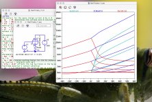
After some little modifications of my recently introduced generic triode spice model, it is now possible to simulate triodes in inverted operating mode.
I guess that's the worldwide first triode spice model allowing this!
kind regards, Adrian Immler
After some little modifications of my recently introduced generic triode spice model, it is now possible to simulate triodes in inverted operating mode.
I guess that's the worldwide first triode spice model allowing this!
kind regards, Adrian Immler
Attachments
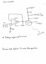
Common Grid Hybrid Inverted Tube Operation
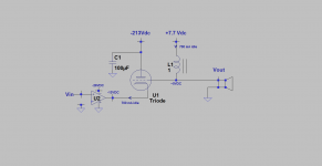
The attached schematic exemplifies the subject title which is pursuant to my post #11. Please note the following:
1. One half of 12AX7A was used.
2. The relevant idle voltages are shown. V[grid-cathode] = [-9.4V] and V[plate-cathode] = 3.36 V.
3. The idle current of the triode is [6.26 mA]. It flows from [+9.62V] through the 1K plate [physical grid] load resistor, across the vacuum between the grid and the cathode and through the power output stage of the OpAmp [LF356N].
4. I measured voltage gain with a digital AC multimeter at 100 Hz. It is defined as the ratio of Vout [0.09 Vac] at the plate [the physical grid] divided by Vin [0.135 Vac] = 0.7
5. This amp did not need "high voltage" to operate. But it is very low power.
6. I still need to unravel its sonic value.
Best
Anton
Attachments
Dear Antoinel
To be honest, in my opinion a tube amplifier stage should either amplify power or act as an impedance converter (or both) to deliver a benefit.
I can't see any of those two jobs fulfilled in your proposed cathode-input grid-output triode stage.
So may you explain me what is the job of your triode stage? Thanks in advance
kind regards, Adrian
Dear Adrian
Thanks for your post. I'll default to your experience and accept that the circuit does not fulfill the job of a tube amplifier.
I wanted to understand [with the circuit] the scope and value of inverted tube operation [ITO] and report. I'll keep looking for value beyond the criteria you mentioned. I am curious about ITO!
Best wishes
Anton
The attached schematic .......
The technical objection is that "this is not an Amplifier".
As you show, the voltage gain is less than unity. The current gain is, by inspection, exactly unity in the DC load (less in the external load). The output is less than the input. It is a fancy way to reduce signal. All the real work comes from the opamp.
Will it "sound like a tube"? I am not sure. The current gain curve is flat. The voltage gain will show some 2nd due to variation of grid impedance. Maybe significantly so here because the DC load is not-large compared to grid resistance.
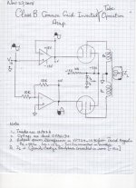
Class B Common Grid Inverted Tube Operating Amp
The attached schematic is for the subject amp on the bench. Works and sounds great. Please note the following for its operation:
1. The dual OpAmps [OPA2134] operate as a phase splitter.
2. At idle, each triode is cut-off; because V(plate-cathode) = 0Vdc).
3. Consider the operation of the upper triode as an example.
3a. As the input signal to its cathode goes positive [shaded half-cycle] two parameters kick in. First, this triode's [V(plate-cathode) goes negative or is reverse biased for proper operation. Second its V(grid-cathode) becomes more negative than its status at idle. Both parameters work together to cut-off the upper triode.
3b. Consider now the simultaneous operation of the bottom triode. The signal at its cathode goes negative during the same time frame of the shaded half-cycle. Two parameters kick in. First, the lower triode's V(plate-cathode) goes positive or is biased for correct operation. Second its V(grid-cathode) goes more positive than its status at idle. Both parameters present the correct conditions for the lower triode to conduct.
3c. The push-pull operation of the two triodes per the above is likle that for a conventional Class B power amp.
4. Thus an output power transformer [OPT] is needed like for a conventional amp. Except the impedance of its primary windings must be low unlike that shown. Why? To allow the highest current to flow through and develop the least voltage drop across the winding so as to maximize the dynamic V(plate-cathode).
Its value is in three parts: It operates Class B, uses a low voltage PSU, and does have the sound character of a tube amp.
Best
Anton
Attachments
A Class B Inverted Tube Operating Amp
The attached schematic is an application of the subject amp. Please note the following:
1. May remind you of a conventional PSU of a vacuum tube power amp.
2. Power is administered to the system via T1 using a Bridge-Tied-Load [BTL] utility power amp. [BTL] is like the AC power line.
3.T1 steps down the voltage to protect the tube. Its out-of-phase signals at the [12 Vac] windings are presented to the plates
physical grids] of the inverted triodes; just like its done in a conventional PSU [point 1].
4. Output power is extracted from the secondary of T2 and drives the headphone load.
5. This amp is bidirectional in this sense. The [12 Vac] secondary windings of T1 go instead to the cathodes. And the [115Vac] primary windings of T2 go instead to plate of the triodes.
This amp sounds great. It is believed that crossover distortion is annoying at low power levels; not here as discerned through the headphones!.
Please ponder the following suggested application for an amp of higher power:
1. The two [12Vac] windings of T1 are connected in parallel.
2. [BTL] drives the resultant [12 Vac] winding. It follows that T1 [now reversed] becomes a voltage step-up transformer.
3. The magnitude of the new induced Plate-Cathode voltage can be high; meaning up to [115Vac] across each winding going to the plate of each inverted triode.
4. Given the appropriate tube, its plate-cathode voltage can be high; but its plate current needs to be low so as not to exceed its SOA.
Best
Anton
Attachments
![Class B [ITO].jpg](/community/data/attachments/662/662975-84504c0bdd81aa8630022d8c7ad3a325.jpg)
I won't use small signal tubes. Because, as people mentioned before, the grid can't handle much current, especially these small signal audio tubes. Look for tubes, which are built for driving into grid current. They might work reliable. (That's why a6080 or tubes like these will destroy easily) So try the 807 for example. Or if you want small tubes, look for Russian tubes with the ending "p-i". These are tubes special build for high power impulsing. Like the 6N1p-i or, better 6N6p-i. I think the 12AX7 is the worst choice. The high mu forces you to have huge voltage swing at the plate. And the grid is not build to drive any current. Hope I could help a bit.
- Status
- This old topic is closed. If you want to reopen this topic, contact a moderator using the "Report Post" button.
- Home
- Amplifiers
- Tubes / Valves
- Inverted Triode ???