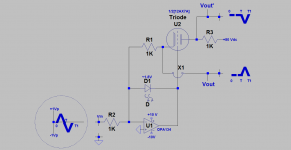
I am enthused to experiment with vacuum tubes. I further hope that you'll find technical value and entertainment in my posts. The attached schematic is a circuit for a functioning Triode Precision Rectifier. Please print it, and note the following details on how it works:
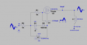
1. The circuit is a cooperation between the operational amp [OPA134] and 1/2 [12AX7A] triode.
2. OPA134 is configured as an inverter; meaning its non inverting input is grounded. It follows that the [physical] inverting input is at virtual ground meaning very close to zero volts like the noninverting input. This state of virtual ground applies at both idle and in operation.
3. The [grid-cathode] of the triode is in the feedback path of OPA134.
4. Note the input signal which has a 2 Vp-p amplitude and has zero crossings at times 0, T and T1 seconds.
5. Let the input signal go positive and peak at [+1Vp] during its duration of 0 to T seconds. Ohm's Law applies; meaning the signal source pushes a 1 mA peak current to flow through the [1K] input resistor; the other end of which is at ~zero volts. This current cannot flow through the physical inverting input. Instead it detours and flows through the LED to be sunk at the power output of OPA134. This current eventually finds its way back to its source ot the input signal.
5b. When the input signal went positive and peaked at +1Vp, the output of OPA134 went negative such that the triode is/becomes cutoff. Because the cathode is at zero volts [virtual ground], and the grid is at ~[-1.8 Vp]. Thus; no current flows to the plate of the triode.
6. Let the input signal go negative and bottom at [-1Vp] during its duration of T to T1 seconds. Ohm's Law applies; meaning the signal source pulls a 1mA peak current to flow through the [1K] input resistor. The invering input of OPA134 cannot supply this current.
6a. When the input signal in point 6 went negative, the output of OPA134 moved towards ground and/or became positive relative to its previous state. Two simultaneous events happen. First, the LED is/becomes reverse-biased and thus no current flows through it. Second, an appropriate grid-cathode voltage develops which allows a ~[1 mA] peak current to flow out of the cathode through the cathode resistor[1K] and finally through the signal input resistor [1K] to the source driver.
6b. Most important is this punch line. The cathode current is identical to the input current and is ensured/guaranteed to be so by OPA134.
7. The rectified output voltage at the cathode [Vout] is referenced to virtual or actual ground [+1Vp]. The rectified output voltage at the plate resistor [1K] is inverted. It is [-1Vp] referenced to ground.
The attached schematic is a building block and/a model for a Class B push-pull power amp to follow.
Best
Anton
Attachments
This is interesting as a mental exercise, but without wishing to appear rude, what's the point?
You can do precision rectifier with the op amp alone (I've made a few similar things in the past)
What is the advantage (if any) in this circuit, in comparison to a op amp precision rectifier circuit/absolute value circuit such as attached image?
You can do precision rectifier with the op amp alone (I've made a few similar things in the past)
What is the advantage (if any) in this circuit, in comparison to a op amp precision rectifier circuit/absolute value circuit such as attached image?
Attachments
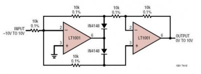
Thanks for your post. You ask reasonable and direct questions. The point of this triode precision rectifier is to build Class B vacuum tube power amps. I did add another precision rectifier to existing designs. But its principal objective is to extend/apply this approach to vacuum tube circuits.
Like you, I've experimented with precision rectifiers and their application in audio amplifiers. The absolute value circuit you showed in your above post does have a [future] application in this thread for another vacuum tube power amp.
Best
Anton
Like you, I've experimented with precision rectifiers and their application in audio amplifiers. The absolute value circuit you showed in your above post does have a [future] application in this thread for another vacuum tube power amp.
Best
Anton
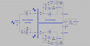
Class B amp using two Triode Precision Rectifiers
Please print the attached schematic and note the following details and explanations:
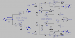
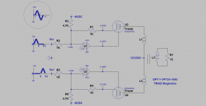
1. The view to the left of the [#] signs vertical barrier shows the schematic of a phase splitter [ PS]. It uses a dual operational amplifier [OPA2134]. PS accepts a music input signal [Vin], and simultaneously outputs two music signals which must be 180 degrees out of phase and must have equal peak to peak amplitudes. PS is an essential and a standard circuit which precedes [as shown] the output stage of a Class B push-pull power amp.
2. The view to the right of the [#] signs vertical barrier shows the schematic of the power output stage. It is comprised of two identical Triode Precision Rectifiers [TPR]. The horizontal [$] signs barrier is an imaginary mirror. It shows that the two [TPRs] are schematically and almost functionally mirror images.
3. The plates of the triodes are loaded with a small utility output power transformer [OPT] as normally done. The B + on its center tap is [+122 Vdc]. OPT has a declared primary impedance = 1 K Ohm, and a secondary impedance = 8 Ohms. The secondary winding is loaded with the two phones of a stereo dynamic headphone which are connected in parallel [mono].
4. The operation of TPR has been explained in post #1.
5. In operation and by example, the lower triode conducts plate current because its [TPR] input signal is negative-going during its duration of 0 to T seconds. The upper triode is cut off; because its simultaneous [TPR] input signal is positive-going during the/its same duration of 0 to T seconds.
6. Thereafter and during the following [T to T1] time interval of the input signals, the operation of the two independent [TPRs] "flip-flops" and/or alternately switch their individual triodes on and off. This is Class B push-pull.
7. Please note the quiescent [encircled] idle voltages within each TPR; simillar. A finite small current is measured [as a voltage drop] at the cathode of each triode!
8. [PS] is driven by the headphone output of a SONY CD player.
9. This Class B headphone amp sounds great. The magnitude of the rectified pulses at the cathodes of the triodes were ~[+1 Vpeak; reference common] for a comfortable SPL. I pushed each cathode up to +3 Vpeak without difficulty/audible degradation.
I'll post a picture of this prototype amp.
Best
Anton
Please print the attached schematic and note the following details and explanations:
1. The view to the left of the [#] signs vertical barrier shows the schematic of a phase splitter [ PS]. It uses a dual operational amplifier [OPA2134]. PS accepts a music input signal [Vin], and simultaneously outputs two music signals which must be 180 degrees out of phase and must have equal peak to peak amplitudes. PS is an essential and a standard circuit which precedes [as shown] the output stage of a Class B push-pull power amp.
2. The view to the right of the [#] signs vertical barrier shows the schematic of the power output stage. It is comprised of two identical Triode Precision Rectifiers [TPR]. The horizontal [$] signs barrier is an imaginary mirror. It shows that the two [TPRs] are schematically and almost functionally mirror images.
3. The plates of the triodes are loaded with a small utility output power transformer [OPT] as normally done. The B + on its center tap is [+122 Vdc]. OPT has a declared primary impedance = 1 K Ohm, and a secondary impedance = 8 Ohms. The secondary winding is loaded with the two phones of a stereo dynamic headphone which are connected in parallel [mono].
4. The operation of TPR has been explained in post #1.
5. In operation and by example, the lower triode conducts plate current because its [TPR] input signal is negative-going during its duration of 0 to T seconds. The upper triode is cut off; because its simultaneous [TPR] input signal is positive-going during the/its same duration of 0 to T seconds.
6. Thereafter and during the following [T to T1] time interval of the input signals, the operation of the two independent [TPRs] "flip-flops" and/or alternately switch their individual triodes on and off. This is Class B push-pull.
7. Please note the quiescent [encircled] idle voltages within each TPR; simillar. A finite small current is measured [as a voltage drop] at the cathode of each triode!
8. [PS] is driven by the headphone output of a SONY CD player.
9. This Class B headphone amp sounds great. The magnitude of the rectified pulses at the cathodes of the triodes were ~[+1 Vpeak; reference common] for a comfortable SPL. I pushed each cathode up to +3 Vpeak without difficulty/audible degradation.
I'll post a picture of this prototype amp.
Best
Anton
Attachments
Last edited:
I was about to say 'I hope he doesn't think this has anything to do with Class B amplifiers'. For Class B you need a smooth transition (except in naive textbooks, written by people who have probably never built an amplifier).Antoinel said:The point of this triode precision rectifier is to build Class B vacuum tube power amps.
I was about to say 'I hope he doesn't think this has anything to do with Class B amplifiers'. For Class B you need a smooth transition (except in naive textbooks, written by people who have probably never built an amplifier).
Thanks DF96 for your post and healthy skepticism. Your underlined statement is accurate. The OpAmp in this Triode Precision Rectifier invests its high open loop gain so as to allow as smooth a transition as possible. It lowers the threshold for this transition as compared with a normal design.
This amp is simple to prototype, and test its hypothesis/limitation.
Best
Anton
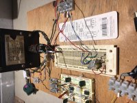
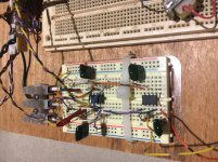
The dark object in the left pic named "Sola Electric" is a regulated 6.3 Vdc [filament] power supply. The +122 V [B+] supply is connected to the upper European connector which feeds the miniature power output transormer [OPT]. The secondary of OPT is loaded with a 10 Ohm resistor.
The right pic gives a close-up view for the circuits for the phase splitter [right OpAmp] and the two Triode Precision Rectifiers [left OpAmp].
Best
Anton
The right pic gives a close-up view for the circuits for the phase splitter [right OpAmp] and the two Triode Precision Rectifiers [left OpAmp].
Best
Anton
Attachments
Lets talk about the transconductance and voltage gain parameters which are commonly used for vacuum tubes. But in this case as they apply to a triode precision rectifier [TPR] of/in the suggested Class B power output stage.
The attached schematic shows only one [TPR] for the output stage so as to simplify the view and the following explanation:
1. Consider [TPR] as the proverbial "Black Box". It has voltages at its input and output nodes. Also, current flows in/out of said nodes.
2. The transconductance of [TPR and not the triode itself] is equal to 1 [the number one] divided by the value of the input resistor R2 [1 K].
2a. The input current flowing through input resistor R2 is equal to the cathode current flowing through R1 and is further equal to plate current. This is guaranteed by the action of the OPAmp.
2b. Input current = Vin divided by R2. Make it by numerical example equal to 1 mA.
2c. TPR Transconductance [TPRgm] = [plate current =/or cathode current =/or input current = 1 mA] divided by Vin which by numerical example is 1 V. The result is equal to [1mA/1 V] or 1/R2
3. [TPR] has a Rectified Voltage Gain [VG] which is equal to the value of Vout [rectified at cathode of triode] divided by one half the peak to peak value of its input signal's voltage.
3a. Why is [TPR's] Rectified VG = [Vout/0.5 Vin]? Because the triode conducts plate current only during the input signal's time interval of [T to T1] seconds which is negative-going.
3b. [TPR] has an additional AC voltage gain. It is equal to Vout' divided by Vin.
3c. Vout' at the plate of this triode is a complete triangle wave spanning its total input time of [0 to T1 seconds]. The component signal in Vout' from [0 to T] was induced by the transformer action of OPT during/from the conduction of the other partner triode. No magic!
The above points suggest that plate current is pristine and/or void of distortion; because it is supervised by the OpAmp; clearly within the bounds of its limitation. This prototype lacks overall negative feedback; in part due to this supervision. Still this amp will need to deal with distortion due to the power output transformer and crossover distortion.
The above points suggest that the transconductance and the voltage gains of both [TPRs] in the power amp can be matched. Highly favorable!
Best
Anton
Attachments
Last edited:
Thanks for your post.
Like you, I've experimented with precision rectifiers and their application in audio amplifiers.
Thanks.
I have used such absolute value circuits, using op amps, in instrumentation applications
Specifically OP27/07 in absolute value circuit, with partnering AD536 for RMS to DC conversion.
This in turn gives a voltage ratio representative of the waveform, or it's deviation from sinusoidal...
Class AB amp using two Triode Precision Rectifiers
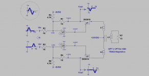
The attached schematic is for a functioning bench prototype. Please note the following changes:
1. The overall view of this suggested Class AB "micro" amp is the same as the Class B micro amp I showed in an earlier post.
2. Each triode idles at a plate current = 68 uA. This was done by using a current source at the inverting input of the OpAmp which is: [-10 Vdc] across 150K. It follows Ohm's Law.
3. This 68 uA idle helps to clean the rectification of sine signals of >10 KHz; because each triode precision rectifier [TPR] is a switching entity. The magnitude of the idle plate = cathode current is adjutable by varying the value of the 150 K resistor.
4. This amp's power output transformer [OPT] is the TRIAD Magnetics toroid power transformer VPT24-1040 [25 VA]. DIYer Lingwendil has a thread in this Forum which is entitled "6SN7 push pull flea amplifier project". He uses therein an Antec toroidal transfer AN-0105. Other contributors to this
thread use toroids in their builds. Great practice; and I am happy to copy it.
5. The headphone [load] is a Grado Prestige. Both phones are wired in mono [~15 Ohms] by Ohmeter.
6. Some DIYers may prefer using a phase-spitter which is simpler [of its insides] than the one I show using OPA2134. DIYer pmillett has a thread in this Forum which is entiled; Posted "NuClassD" amp design : 50W hybrid Class-D / Korg Nutube He shows the schematic of this amp in the link of post #1. Therein, pmillett uses [after the vacuum tube stage] an FET as the phase splitter. Its out-of-phase output signals are further buffered with two additional FETs for presentation to the Class D chip. An approach like that of pmillet' using FETs may be useful in [TPR] circuits. Afterall, some may view/consider FETs to be solid state vacuum tubes.
7. I'll show another independent method to forward bias the triodes.
8. This Class AB amp like its earlier Class B parent doubles as a Full-Cycle Precision Rectifier. Its two output [rectified] signals are at the cathodes of the triodes. They are in phase; thanks to the phase spitter. Most important is to note the time-scale of each signal. Each is displaced in time and each shows when the triode is switched ON. When one triode is ON, its partner is OFF.
This amp sounds great, and is a bit louder than its Class B parent.
Best
Anton
Attachments
Last edited:
A new experimental micro amp
May I bring your attention to my thread in the Pass Labs Forum which is entitled Class aP amplification. It deals with a subject matter like this one thread; but with a sole focus on solid state devices. This thread is a resource. It has info/schematics on generating analog pulses [aP]; which is the same as the Full Cycle Rectified Signals terminology that I am using here.
The attached schematic shows only the power output stage to simplify the view. This view is like others which I've already shown. The following shows it to be different:
1. Each triode idles at ~1.7 mA each. This current is the numerical value of the voltage at each's cathode. This idle current is enabled/generated at the inverting input of the OpAmp by using the [-8V ]voltage source and the [4.7K] input resistor[-8V divided by 4.7 K].
2. Now imagine a load line for each triode on its characteristic curve. This idle operating point [~1.7 mA] sits at the top left part of this load line. The objective of this amp's operation is to slide this operating point along the load line from the top left to the bottom right. Meaning this operation will turn off each tube; but be mindful not to cut it off.
3. In operation, each triode receives a half-wave [rectified] signal from a Full-Cycle Rectified Signal generator [not shown]. I have shown in the previous post how to derive these two specific rectified rectified positive-going signals. Note the timing of each rectified signal. When the upper triode is active, the bottom one idles [at ~1.7 mA] and waits patiently for its turn to process its input signal.
4. The rectified input signals are inverted at the output of the respective OpAmps. The resultant negative-going rectified signal is presented to the grid of the triode. It turns it progressively; but not fully off which is the desired outcome.
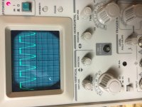
5. The scope view shows this outcome [please rotate it]. At idle, the trace is up at ~1.5 Vdc. A ~15 KHz negative-going signal is measured at the cathode of either triode. I did not allow the inverted pointed peaks to reach zero. Clipping will be observed.
This amp sounds great through headphones.
Best
Anton
May I bring your attention to my thread in the Pass Labs Forum which is entitled Class aP amplification. It deals with a subject matter like this one thread; but with a sole focus on solid state devices. This thread is a resource. It has info/schematics on generating analog pulses [aP]; which is the same as the Full Cycle Rectified Signals terminology that I am using here.
The attached schematic shows only the power output stage to simplify the view. This view is like others which I've already shown. The following shows it to be different:
1. Each triode idles at ~1.7 mA each. This current is the numerical value of the voltage at each's cathode. This idle current is enabled/generated at the inverting input of the OpAmp by using the [-8V ]voltage source and the [4.7K] input resistor[-8V divided by 4.7 K].
2. Now imagine a load line for each triode on its characteristic curve. This idle operating point [~1.7 mA] sits at the top left part of this load line. The objective of this amp's operation is to slide this operating point along the load line from the top left to the bottom right. Meaning this operation will turn off each tube; but be mindful not to cut it off.
3. In operation, each triode receives a half-wave [rectified] signal from a Full-Cycle Rectified Signal generator [not shown]. I have shown in the previous post how to derive these two specific rectified rectified positive-going signals. Note the timing of each rectified signal. When the upper triode is active, the bottom one idles [at ~1.7 mA] and waits patiently for its turn to process its input signal.
4. The rectified input signals are inverted at the output of the respective OpAmps. The resultant negative-going rectified signal is presented to the grid of the triode. It turns it progressively; but not fully off which is the desired outcome.
5. The scope view shows this outcome [please rotate it]. At idle, the trace is up at ~1.5 Vdc. A ~15 KHz negative-going signal is measured at the cathode of either triode. I did not allow the inverted pointed peaks to reach zero. Clipping will be observed.
This amp sounds great through headphones.
Best
Anton
Attachments
A FET micro amp like a vacuum tube counterpart
I replaced 12AX7A in the amp understudy with two N-channel FETs as shown in the attached schematic. This clone amp has the following value:
1. A first step to understand the operation of its circuit as a heads-up [confidence builder] leading to a similar one using vacuum tubes. It allows one to work with benign low voltage PSUs.
2. FET lived up to its reputation of a solid state vacuum tube [pentode]. This circuit and the one I showed in the past post [using 12AX7A] operated in an identical objective manner.
3. I chose two mismatched FETs. They had different values of Idss. The value of the different voltages at their gates [0.442V and 0.695V] in this circuit is the indicator of this gross mismatch. The two triodes in the past schematic were "matched" way better [1.303V and 1.380V at grids] than the FETs.
4. Despite using mismatched FETs, the trans-conductance and voltage gain of one side of the circuit [OpAmp plus its FET] were similar if not identical to the corresponding parameters for the partner side.
4a. Mr Roger Modjeski prefers the two tubes to be inherently matched for trans-conductance and voltage gain. The OpAmps in this situation enforce a parameter match for both halves of this circuit despite an inherent mismatch in the used FETs [or vacuum tubes].
5. Like in past post, the idle operating point of each FET is at the top left of its imaginary load-line. In use, this operating point slides towards the bottom right of this load line; meaning it moves the generous idle current towards cutoff. This is illustrated with the signals at the source of the FETs. The FET [or tube] cuts off when its cathode/source voltage reaches zero volts. This is another way to operate with the same outcome; may call it an Inverse Class B!
This amp sounds great; albeit different from that using 12AX7A.
Best
Anton
Attachments
- Status
- This old topic is closed. If you want to reopen this topic, contact a moderator using the "Report Post" button.
- Home
- Amplifiers
- Tubes / Valves
- Experimenting with Vacuum Tubes