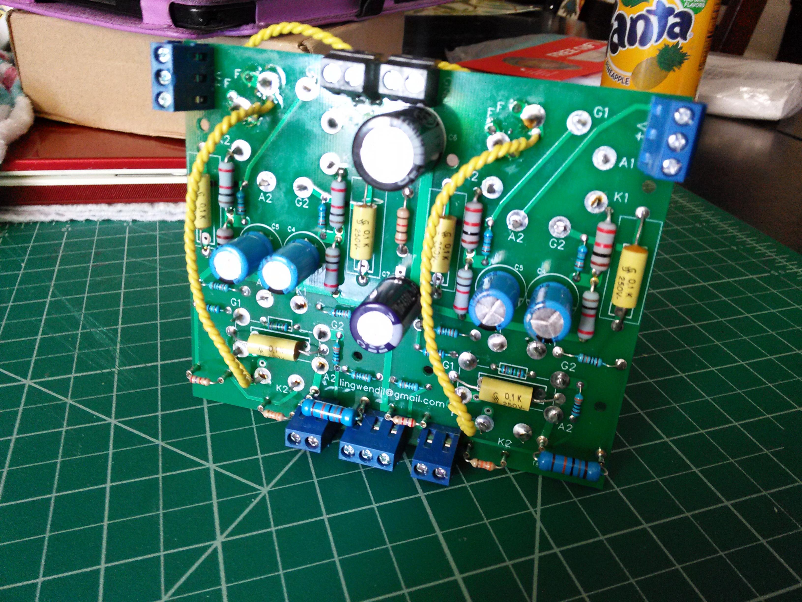
I've built a small stereo kitchen amp using a pair of PCL82s.
My issue is it's way too sensitive. I'm going to drive it from a RaspberryPi audio card with 2Vrms max output, using the card's hardware level control.
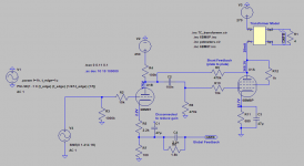
The output from the triode driver stage (U1B) overdrives the triode-connected pentode stage (U1A) when the input signal is still very low - well below 1 Vrms, as suggested by the datasheets.
So I need to reduce the gain from U1B:
I'll also use some GNFB to try and flatten the response from the tiny OTs.
The plate to plate feedback, via R9, sims quite nicely and provides an eloquent solution - not needing a nasty pot...
Are there any further issues with this? Or other approaches to take?
My issue is it's way too sensitive. I'm going to drive it from a RaspberryPi audio card with 2Vrms max output, using the card's hardware level control.
The output from the triode driver stage (U1B) overdrives the triode-connected pentode stage (U1A) when the input signal is still very low - well below 1 Vrms, as suggested by the datasheets.
So I need to reduce the gain from U1B:
- remove the bypass cap C1, and
- add some plate to plate / shunt / Schade feedback via R9, or
- just add a dual gang volume pot in front of R3
I'll also use some GNFB to try and flatten the response from the tiny OTs.
The plate to plate feedback, via R9, sims quite nicely and provides an eloquent solution - not needing a nasty pot...
Are there any further issues with this? Or other approaches to take?
Attachments
I would place a 470k resistor in series with the input on to R2 and decrease the value of R3 to a suitable resistance of around 47k.
I have never been a fan of two NFB loops and would not fit R9.
If there is still too much gain, place a series resistor of 1M in series with the cold end of C2 further reducing the gain another 6dB.
I have never been a fan of two NFB loops and would not fit R9.
If there is still too much gain, place a series resistor of 1M in series with the cold end of C2 further reducing the gain another 6dB.
Thanks all. I spent a day trying to get a flat(er) response or even a square wave that remains a square wave at the output using various levels of feedback resistor & capacitor. But was getting nowhere. The phase shift was getting to >180 with still >0 gain which I believe leads to instability and is something to be avoided...
These OTs are little things from old radios - cheap from a well-known auction site. Perhaps I'll remove the feedback and just let live.
These OTs are little things from old radios - cheap from a well-known auction site. Perhaps I'll remove the feedback and just let live.
Good advice!Just settle on a pleasant sound.
I've yet to build them... Going to make a pair of mini Karlsonators from foam board.With high efficiency speakers you might not need the first stage at all.
Yes, I was hoping to do all the volume control from the Pi using Moode. I can go in to the underlying code (ALSA or MDP) to lower what "100%" output is. But was keeping that as a last resort - from a gain staging point of view.Does your RPi's DAC have any adjustments for the taper of its hardware volume control? Maybe the app you're using has a way of attenuating the output before it gets to the amp?
I should have bread-boarded it before ordering the PCBs... I was too eager.
I've yet to build them... Going to make a pair of mini Karlsonators from foam board.
Very good choice
")
Attached are my first set using the TC9FD. I also built a set using two Faital Pro 3FE25-16 in parallel per box. Highly recommended. They are in daily use with my 6SN7 flea amplifier, and are sensitive enough that a watt is very, very loud.
I forget what the RPi can put out at max signal output. What pi DAC are you using? I think the majority of them do something like 900mV peak, depending on the exact chip used.
Attachments
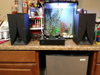
Very nice indeed. I bought double the number of foam sheets to allow for a mess-up or two... I've two Faital Pro 3FE25 (4 ohm) to use. So a slight mis-match to the PCL82 if the OTs are what I think they are (~6k:6 ohm).Very good choice
Attached are my first set using the TC9FD. I also built a set using two Faital Pro 3FE25-16 in parallel per box. Highly recommended. They are in daily use with my 6SN7 flea amplifier, and are sensitive enough that a watt is very, very loud.
I'm using an IQaudIO Pi-DACZero: Pi-DACZero I2S audiophile sound card for Raspberry Pi Zero The specs say 2Vrms output using a TI Burr Brown 32-bit/384kHz DAC (TI PCM5122)I forget what the RPi can put out at max signal output. What pi DAC are you using? I think the majority of them do something like 900mV peak, depending on the exact chip used.
I use its bigger brother (the Pi-DAC+, at full 0Db output, with volume controlled by my preamp) with my Millett's DCPP Engineer's Amplifier and it sounds great - and the output is considerably louder than my other sources.
I'm in the habit of running a single twisted pair (from plenum-rated CAT6 cable, since I already use it for other small signal wiring) from the speaker output terminals directly to/across the cathode resistor of the input stage, this way it is referenced right at the input (and it carries trivially small loop current) and you have to run the feedback wire there anyway. Just slip the feedback resistor between the cathode resistor and the wire. Easy peasy
In really high gain applications or noisy environments I've also done this with coaxial cable, such as RG-174U, it's thin and flexible, so easy enough to route.
In really high gain applications or noisy environments I've also done this with coaxial cable, such as RG-174U, it's thin and flexible, so easy enough to route.
Trist- In order to use NGFB, you must ground one side of the output trans. secondary. Otherwise, there is no reference for it back to the v. amp. tube. Maybe that's why you couldn't tame it at all.
I'm in the habit of running a single twisted pair (from plenum-rated CAT6 cable, since I already use it for other small signal wiring) from the speaker output terminals directly to/across the cathode resistor of the input stage, this way it is referenced right at the input (and it carries trivially small loop current) and you have to run the feedback wire there anyway. Just slip the feedback resistor between the cathode resistor and the wire. Easy peasy
Thanks both. I added screw terminals for speaker grounding & feedback to the PCB design - in keeping with my goal of making things easy to swap around and insert / remove. I'll double check my connections though as there's alway a chance I missed them off!
I've also having fun with LTspice and the THD Analyser tool - looking at the differing levels of distortion reduction that can be achieved by implementing either feedback loop & driver bias point selection.
In addition, I've been looking back at some of Pete Millett's schematics and how he has both plate to plate and GNFB implemented at the same time. I might try it and see what happens sound-wise...
Attachments
Screw terminals are nice, I really wish more would use them on their PCB designs when I first started building years ago. It seems most of the boards I would find simly had holes for wire leads.
For my flea amp PCB I made sure to have the wiring that leads off board use easy to find screw terminals, and the only wiring on-baord was the twisted pair jumpers for AC heater wiring. If using DC wire links would be all that was needed. I wanted people to be able to stuff the board, mount everything in the chassis, and then screw down all the wiring-
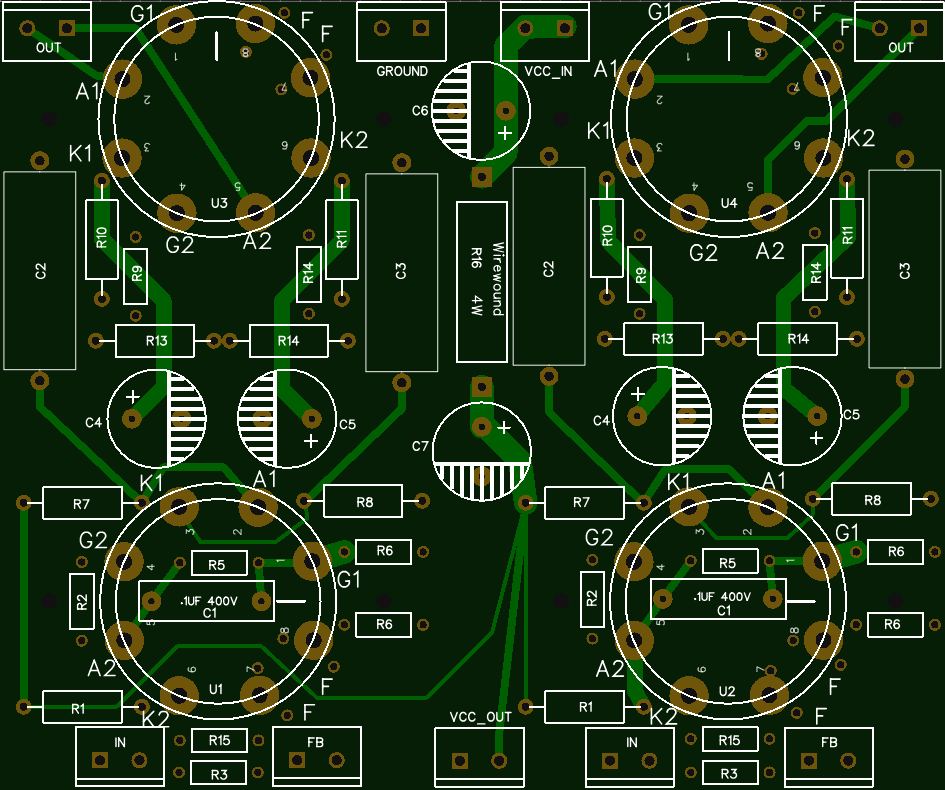
(this is my first PCB design, don't laugh lol
For my flea amp PCB I made sure to have the wiring that leads off board use easy to find screw terminals, and the only wiring on-baord was the twisted pair jumpers for AC heater wiring. If using DC wire links would be all that was needed. I wanted people to be able to stuff the board, mount everything in the chassis, and then screw down all the wiring-
(this is my first PCB design, don't laugh lol
Minimize distortion via FFT & driver bias?
I like the little turrets. That would be useful for resistors that need to dissipate more heat...
I hope to get this amp 'finished' this coming weekend. I'm going to add a 470k shunt feedback resistor and see how that sounds / works with getting suitable input sensitivity.
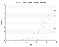
But for the driver stage bias, since I have a trim pot, I was going to inject a sine wave (1 kHz, at a just-clipping level) and alter the bias to get minimal overall distortion as viewed on a FFT of the output signal.
Is this a sensible approach? Proof will be in the listening I guess...
From the transfer function curves (attached - taken from one of my actual valves using my uTracer) it looks like 1.25-1.5 V is a good region. But other designs with the PCL82/ECL82 tend to put this higher at >2V. Or maybe I'm overthinking this...
I like the little turrets. That would be useful for resistors that need to dissipate more heat...
I hope to get this amp 'finished' this coming weekend. I'm going to add a 470k shunt feedback resistor and see how that sounds / works with getting suitable input sensitivity.
But for the driver stage bias, since I have a trim pot, I was going to inject a sine wave (1 kHz, at a just-clipping level) and alter the bias to get minimal overall distortion as viewed on a FFT of the output signal.
Is this a sensible approach? Proof will be in the listening I guess...
From the transfer function curves (attached - taken from one of my actual valves using my uTracer) it looks like 1.25-1.5 V is a good region. But other designs with the PCL82/ECL82 tend to put this higher at >2V. Or maybe I'm overthinking this...
Attachments
Load lines are the usual way of designing a triode stage. The curves you have shown are fine for designing a stage which will work into a short circuit, as then you need transconductance linearity. If you have enough anode-to-anode feedback then the triode will see only a small resistance as load so then transconductance matters.
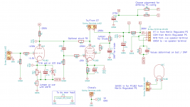
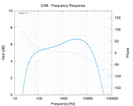
So I managed to make the changes this weekend. Attached is a quick frequency sweep.
My HT is 255V with the driver bias set to 2.5V (gave lowest distortion whilst keeping a sensible output), 185V on the plate. The main stage is biased at 20V.
I get a good 1 Vrms input with 'clean' looking output. So that's an improvement. An FFT at 0.5 Vpp input gives a THD of <1.5ish%. Not great compared to my DCPP (0.15%). The 2nd harmonic was 45db below the fundamental, 3rd a bit below that. This was all done very quickly so will need to redo them later and experiment a bit.
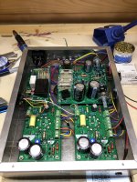
I also added in a mini-DIN (6 pin) connector (seen on the left of the picture) for inputs & control. This gives me L, R, GND & 5V, DGND, on/off - as this will power a RaspberryPi situated at the other end of the serial cable. The Pi will control a relay in the amp to switch the mains to the power supply whenever audio is playing.
I've yet to 'hear' this amp as the mini-Karlsonators are a pile of foamcore parts and the Pi / code to run on it has yet to be put together. Hopefully those will be complete soon!
My HT is 255V with the driver bias set to 2.5V (gave lowest distortion whilst keeping a sensible output), 185V on the plate. The main stage is biased at 20V.
I get a good 1 Vrms input with 'clean' looking output. So that's an improvement. An FFT at 0.5 Vpp input gives a THD of <1.5ish%. Not great compared to my DCPP (0.15%). The 2nd harmonic was 45db below the fundamental, 3rd a bit below that. This was all done very quickly so will need to redo them later and experiment a bit.
I also added in a mini-DIN (6 pin) connector (seen on the left of the picture) for inputs & control. This gives me L, R, GND & 5V, DGND, on/off - as this will power a RaspberryPi situated at the other end of the serial cable. The Pi will control a relay in the amp to switch the mains to the power supply whenever audio is playing.
I've yet to 'hear' this amp as the mini-Karlsonators are a pile of foamcore parts and the Pi / code to run on it has yet to be put together. Hopefully those will be complete soon!
Attachments
- Status
- This old topic is closed. If you want to reopen this topic, contact a moderator using the "Report Post" button.
- Home
- Amplifiers
- Tubes / Valves
- Reducing input sensitivity - pot or shunt feedback?