


Why do you say even though? Did anyone tell you that KT77's are inferior to other power tubes?It is better than expected even though output tubes were JJ KT77.
Your results are excellent, btw!
Best regards!
In my design (2xKT88 B+420V CFB Raa4K 40W/4R) OLG is 34dB and CLG 21dB. The driver required voltage swing is 140Vpp.
Can you then confirm that the amount of CFB is indeed what they claim? They state 10% of Ra which is a rather unusual way to define it. That's 24% CFB in terms of turn (or voltage) ratio between cathode and total anode + cathode.
A while ago someone else was maligning about those OPT's hinting they are a bad copy of the Plitrons and so 10% is turn (or voltage) ratio.
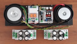
Your amp design and test results confirm my experience building with with Toroidy CFB transformers. They are a very nice transformer. Will use them again. My next design will use John Broskie "Blumlein Garter Revisited". This will ensure good current balance in the transformer, as I understand that balance is more critical with Toroidal transformers.
Last edited:
Can you then confirm that the amount of CFB is indeed what they claim? They state 10% of Ra which is a rather unusual way to define it. That's 24% CFB in terms of turn (or voltage) ratio between cathode and total anode + cathode.
A while ago someone else was maligning about those OPT's hinting they are a bad copy of the Plitrons and so 10% is turn (or voltage) ratio.
see this
LTSpice model for a commercial toroidal output transformer

Ah OK, but what is not true is what they STATe in their website!!! It's not me. I had not noticed your reply in that thread. So Peter was right. I asked directly to Toroidy about that funny definition and they replied that it was indeed 10% Ra. Now it's clear that they do NOT know what they are talking about. I have to admit that Peter was right and they have probably copied the Plitron transformer. Bad copy of course, because the Plitron has quite better bandwidth and headroom.
Just to avoid mis-understandings and discussions I copy and paste their response here again:
"Thank You for contact us.
There are two cathode windings - one for each half of the primary winding.
TTG-CFB4000PP has a 4k Raa (anode to andode) - 2k between the anode and the center tap.
Each CFB winding is calculated as a 10% of a half, so 10% of a 2k."
That's quite clear. And it means 24% CFB which is not what it is in reality. Enough for me to NOT trust all the other specs. It might be cheap respect to other options but not worth the trouble for me. For others it might be. At their own risk of course....
Last edited:
- Status
- This old topic is closed. If you want to reopen this topic, contact a moderator using the "Report Post" button.
- Home
- Amplifiers
- Tubes / Valves
- PP CFB toroidy OPT