Hi,
I'm building my second VT power amplifier (designing first). It consists of
- two OPS boards
- two DRIVER boards
- 6.3VDC PSU (DRIVER heaters)
- AC power control board
- 5V/12V PSU
- 120VA transformer for heaters
- 200VA transformer for HT and bias PSUs
- two toroidal CFB OPTs from toroidy.pl
- metal chassis
Maybe there will be also
- one analog meter for bias setting
- remote control board (on/off, volume)
Almost all components are ready. I'm about to design DRIVER board and I want to know your opinion. There are two DC coupled LTPs supported by CCS and powered by mosfet regulators. First stage E88CC, second stage E88CC or ECC99, heaters have configurable jumpers. Regards NFB, you can have global or/and local "Schade" feedback.
Last edited:


6550 cathode feadback
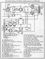
I have two toroidal CFB OPTs from toroidy.pl for 6550 /KT88.
I hope to use the attached circuits Still to decide which one} capable of 180 volts RMS into 47k load {47K is max for current 6550 and KT88 tubes} using the 5687. A toroid power transformer and solid state rectifiers
I have two toroidal CFB OPTs from toroidy.pl for 6550 /KT88.
I hope to use the attached circuits Still to decide which one} capable of 180 volts RMS into 47k load {47K is max for current 6550 and KT88 tubes} using the 5687. A toroid power transformer and solid state rectifiers
Attachments

Nice design. I built a CFB amp using Toroidy CFB transformers and they worked well, but did have an initial issue with instability at low frequency. (High frequency was fine). I initally suspected power supply but on testing observed slight more phase shift a 10 Hz that I was expecting. I solved problem by using Normal Koren design concepts and instead of global feedback to the first stage I changed to feedback to the drivers.

See thread PP amp with Toriody Transformers and 7591A
Note that schematic changed on post 28. Samples of output into 8 ohms parrelled with 1uf. I like the look of your design...but I choose the 7591a tube as this is easier to drive given that the use of CFB the drive requirements double.
Note that schematic changed on post 28. Samples of output into 8 ohms parrelled with 1uf. I like the look of your design...but I choose the 7591a tube as this is easier to drive given that the use of CFB the drive requirements double.


My understanding is that Toriodal transformers are more sensitive to DC imbalance in the output pair. John Broskie (Tubecad) proposed a Cross-Refenced Auto Bias Circuit in his thread "Blumlein’s garter circuit revisited"
I will try this in my next design (also using Toriody transformers)
I will try this in my next design (also using Toriody transformers)


My understanding is that Toriodal transformers are more sensitive to DC imbalance in the output pair. John Broskie (Tubecad) proposed a Cross-Refenced Auto Bias Circuit in his thread "Blumlein’s garter circuit revisited"
I will try this in my next design (also using Toriody transformers)
Garter bias works very well, and I use it a great deal. I like it enough that my Flea amp uses it, and to be designing a PCB for it with EL84/86 types- 6N2P/6CW5 design with toroidal outputs
- Status
- This old topic is closed. If you want to reopen this topic, contact a moderator using the "Report Post" button.
- Home
- Amplifiers
- Tubes / Valves
- PP CFB toroidy OPT